Content .. 1386 1387 1388 1389 ..
Infiniti G35 (V35) Sedan. Manual - part 1388
TM-244
< ON-VEHICLE REPAIR >
[5AT: RE5R05A]
CONTROL VALVE WITH TCM
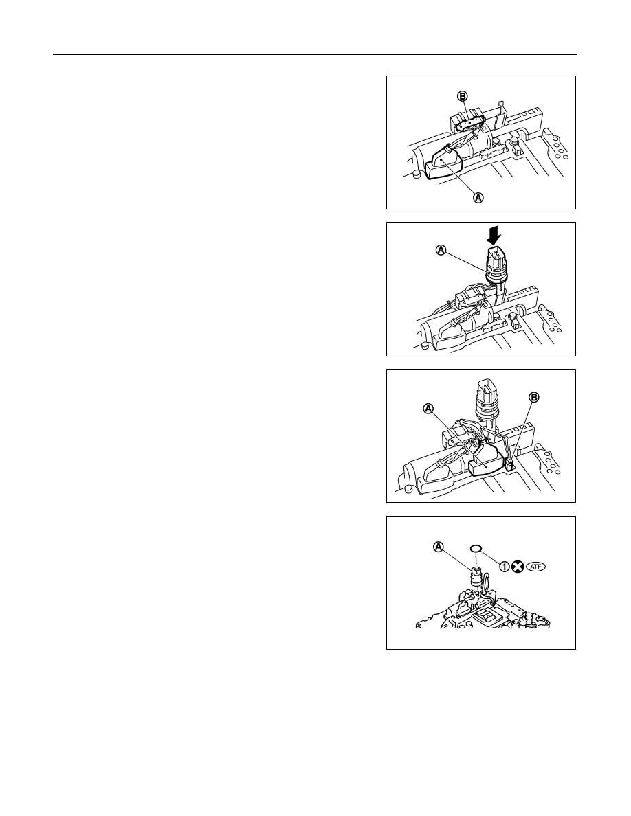
INSTALLATION
1.
Connect TCM connector (A) and park/neutral position switch
connector (B).
2.
Install A/T assembly harness connector (A) to control valve with
TCM.
3.
Connect TCM connectors (A) and (B).
4.
Install new O-ring (1) in A/T assembly harness connector (A).
JPDIA0018ZZ
JPDIA0019ZZ
JPDIA0016ZZ
JPDIA0015ZZ