Infiniti G20 (P11). Manual - part 261


  Index      Infiniti     Infiniti G20 (P11) - service repair manual 1999-2002 year


Search            


Content   ..  259  260  261  262   ..


Infiniti G20 (P11). Manual - part 261


Diagnostic Procedure

NCEC0500

1

CHECK INPUT SIGNAL CIRCUIT

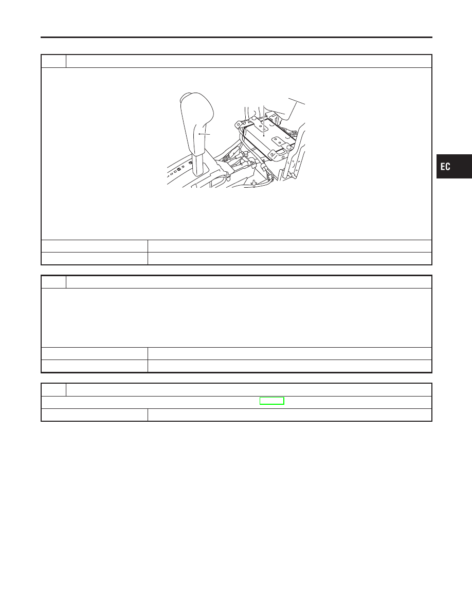
1. Turn ignition switch “OFF”.
2. Disconnect ECM harness connector and TCM (Transmission control module) harness connector.

Selector
lever

TCM (Transmission
control module)

SEF313W

3. Check harness continuity between ECM terminal 10 and TCM terminal 7, ECM terminal 19 and TCM terminal 8, ECM

terminal 54 and terminal 5, ECM terminal 55 and TCM terminal 6, ECM terminal 56 and TCM terminal 9.
Refer to Wiring Diagram.

Continuity should exist.

OK or NG

OK

©

GO TO 2.

NG

©

Repair harness or connectors.

2

CHECK INPUT SIGNAL CIRCUIT

1. Check harness continuity between ECM terminal 10 and ground, ECM terminal 19 and ground, ECM terminal 54 and

ground, ECM terminal 55 and ground, ECM terminal 56 and ground.
Refer to Wiring Diagram.

Continuity should not exist.

2. Also check harness for short to power.

OK or NG

OK

©

GO TO 3.

NG

©

Repair short to ground or short to power in harness.

3

CHECK INTERMITTENT INCIDENT

Refer to “TROUBLE DIAGNOSIS FOR INTERMITTENT INCIDENT”, EC-146.

©

INSPECTION END

GI

MA

EM

LC

FE

CL

MT

AT

AX

SU

BR

ST

RS

BT

HA

SC

EL

IDX

DTC P0600 A/T CONTROL

Diagnostic Procedure

EC-455

SEF093X

Component Description

NCEC0295

The ECM consists of a microcomputer and connector for signal
input and output and for power supply. The ECM controls the
engine.

On Board Diagnosis Logic

NCEC0296

DTC No.

Malfunction is detected when ...

Check Items (Possible Cause)

P0605

I

ECM calculation function is malfunctioning.

I

ECM

SEF058Y

DTC Confirmation Procedure

NCEC0297

NOTE:
If “DTC Confirmation Procedure” has been previously conducted,
always turn ignition switch “OFF” and wait at least 10 seconds
before conducting the next test.

With CONSULT-II

1)

Turn ignition switch “ON”.

2)

Select “DATA MONITOR” mode with CONSULT-II.

3)

Start engine.

4)

Run engine for at least 30 seconds at idle speed.

5)

If 1st trip DTC is detected, go to “Diagnostic Procedure”,
EC-457.

With GST

Follow the procedure “With CONSULT-II” above.

DTC P0605 ECM

Component Description

EC-456

Diagnostic Procedure

NCEC0298

1

INSPECTION START

With CONSULT-II

1. Turn ignition switch “ON”.
2. Select “SELF DIAG RESULTS” mode with CONSULT-II.
3. Touch “ERASE”.
4. Perform “DTC Confirmation Procedure”.

See EC-456.

5. Is the 1st trip DTC P0605 displayed again?

With GST

1. Turn ignition switch “ON”.
2. Select MODE 4 with GST.
3. Touch “ERASE”.
4. Perform “DTC Confirmation Procedure”.

See EC-456.

5. Is the 1st trip DTC P0605 displayed again?

Yes or No

Yes

©

GO TO 2.

No

©

INSPECTION END

2

REPLACE ECM

1. Replace ECM.
2. Perform initialization of IVIS (NATS) system and registration of all IVIS (NATS) ignition key IDs. Refer to “IVIS (INFINITI

VEHICLE IMMOBILIZER SYSTEM — NATS)”, EC-81.

3. Perform “Idle Air Volume Learning”, EC-65.

Is the result CMPLT or INCMP?

CMPLT or INCMP

CMPLT

©

INSPECTION END

INCMP

©

Follow the construction of “Idle Air Volume Learning”.

GI

MA

EM

LC

FE

CL

MT

AT

AX

SU

BR

ST

RS

BT

HA

SC

EL

IDX

DTC P0605 ECM

Diagnostic Procedure

EC-457

On Board Diagnosis Logic

NCEC0568

Engine coolant temperature has not risen enough to open the ther-
mostat even though the engine has run long enough.
This is due to a leak in the seal or the thermostat open stuck.
Malfunction is detected when the engine coolant temperature does
not reach to specified temperature even though the engine has run
long enough.

Possible Cause

NCEC0569

I

Thermostat function

I

Leakage from sealing portion of thermostat

I

Engine coolant temperature sensor

DTC Confirmation Procedure

NCEC0570

NOTE:
If “DTC Confirmation Procedure” has been previously conducted,
always turn ignition switch “OFF” and wait at least 10 seconds
before conducting the next test.
TESTING CONDITION:

I

For best results, perform at ambient temperature of –10°C
(14°F) or higher.

I

For best results, perform at engine coolant temperature of
–10°C (14°F) to 60°C (140°F).

WITH CONSULT-II

NCEC0570S01

1)

Replace thermostat with new one. Refer to LC-12, “Thermo-
stat”. Use only a genuine NISSAN thermostat as a replace-
ment. If an incorrect thermostat is used, the MIL may come on.

2)

Turn ignition switch “ON”.

3)

Select “COOLAN TEMP/S” in “DATA MONITOR” mode with
CONSULT-II.

4)

Check that the “COOLAN TEMP/S” is above 60°C (140°F).
If it is below 60°C (140°F), go to following step.
If it is above 60°C (140°F), stop engine and cool down the
engine to less than 60°C (140°F), then retry from step 1.

5)

Drive vehicle for 10 consecutive minutes under the following
conditions.

VHCL SPEED SE

80 - 120 km/h (50 - 75 MPH)

If 1st trip DTC is detected, go to “Diagnostic Procedure”,
EC-459.

WITH GST

NCEC0570S02

1)

Follow the prodedure “WITH CONSULT-II” above.

DTC P1126 THERMOSTAT FUNCTION

On Board Diagnosis Logic

EC-458


Content   ..  259  260  261  262   ..