Infiniti G20 (P11). Manual - part 259
Wiring Diagram
NCEC0292
TEC716
GI
MA
EM
LC
FE
CL
MT
AT
AX
SU
BR
ST
RS
BT
HA
SC
EL
IDX
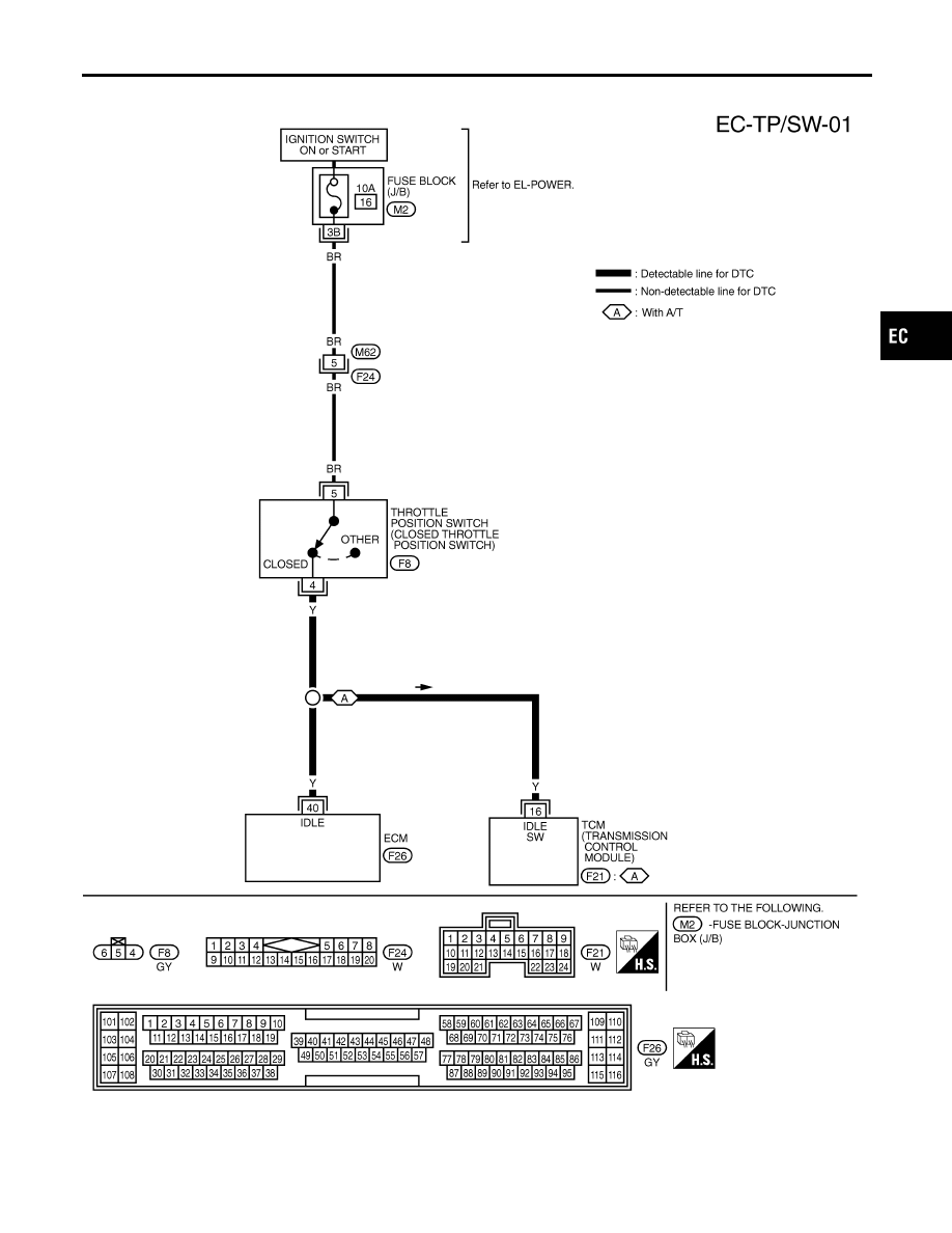
DTC P0510 CLOSED THROTTLE POSITION SWITCH
Wiring Diagram
EC-447
|
|
|
Wiring Diagram NCEC0292 TEC716 GI MA EM LC FE CL MT AT AX SU BR ST RS BT HA SC EL IDX DTC P0510 CLOSED THROTTLE POSITION SWITCH Wiring Diagram EC-447 |