Infiniti G20 (P11). Manual - part 192
DTC Confirmation Procedure
NCEC0083
Perform “PROCEDURE FOR MALFUNCTION A” first. If the 1st
trip DTC cannot be confirmed, perform “PROCEDURE FOR
MALFUNCTION B”. If there is no problem on “PROCEDURE
FOR MALFUNCTION B”, perform “PROCEDURE FOR MAL-
FUNCTION C”.
NOTE:
If “DTC Confirmation Procedure” has been previously conducted,
always turn ignition switch “OFF” and wait at least 10 seconds
before conducting the next test.
PROCEDURE FOR MALFUNCTION A
NCEC0083S01
CAUTION:
Always drive vehicle at a safe speed.
TESTING CONDITION:
I
Before performing the following procedure, confirm that
battery voltage is more than 10V at idle.
I
This test may be conducted with the drive wheels lifted in
the shop or by driving the vehicle. If a road test is
expected to be easier, it is unnecessary to lift the vehicle.
SEF065Y
With CONSULT-II
1)
Turn ignition switch “ON” and select “DATA MONITOR” mode
with CONSULT-II.
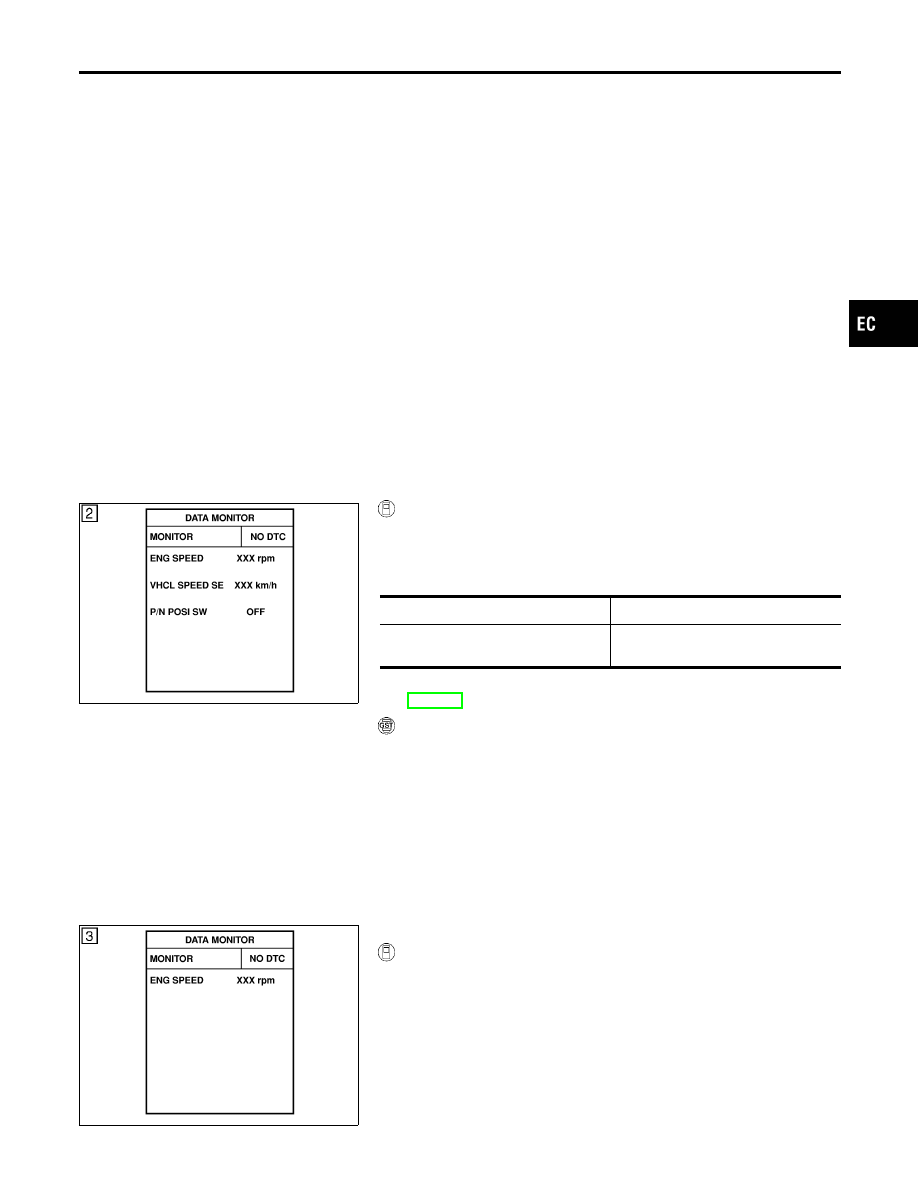
2)
Start engine and maintain the following conditions for at least
5 consecutive seconds.
VHCL SPEED SE
More than 4 km/h (2 MPH)
Selector lever
Suitable position except “P” or “N”
position
3)
If 1st trip DTC is detected, go to “Diagnostic Procedure”,
EC-184.
With GST
Follow the procedure “With CONSULT-II” above.
SEF058Y
PROCEDURE FOR MALFUNCTION B
NCEC0083S02
With CONSULT-II
1)
Turn ignition switch “ON”.
2)
Select “DATA MONITOR” mode with CONSULT-II.
3)
Start engine and let it idle for at least 10 seconds.
If idle speed is over 1,000 rpm, maintain the following condi-
tions for at least 10 seconds to keep engine speed below 1,000
rpm.
GI
MA
EM
LC
FE
CL
MT
AT
AX
SU
BR
ST
RS
BT
HA
SC
EL
IDX
DTC P0120 THROTTLE POSITION SENSOR
DTC Confirmation Procedure
EC-179