Infiniti FX35, FX50 (S51). Manual - part 557
REAR OIL SEAL
DLN-63
< REMOVAL AND INSTALLATION >
[TRANSFER: ETX13C]
C
E
F
G
H
I
J
K
L
M
A
B
DLN
N
O
P
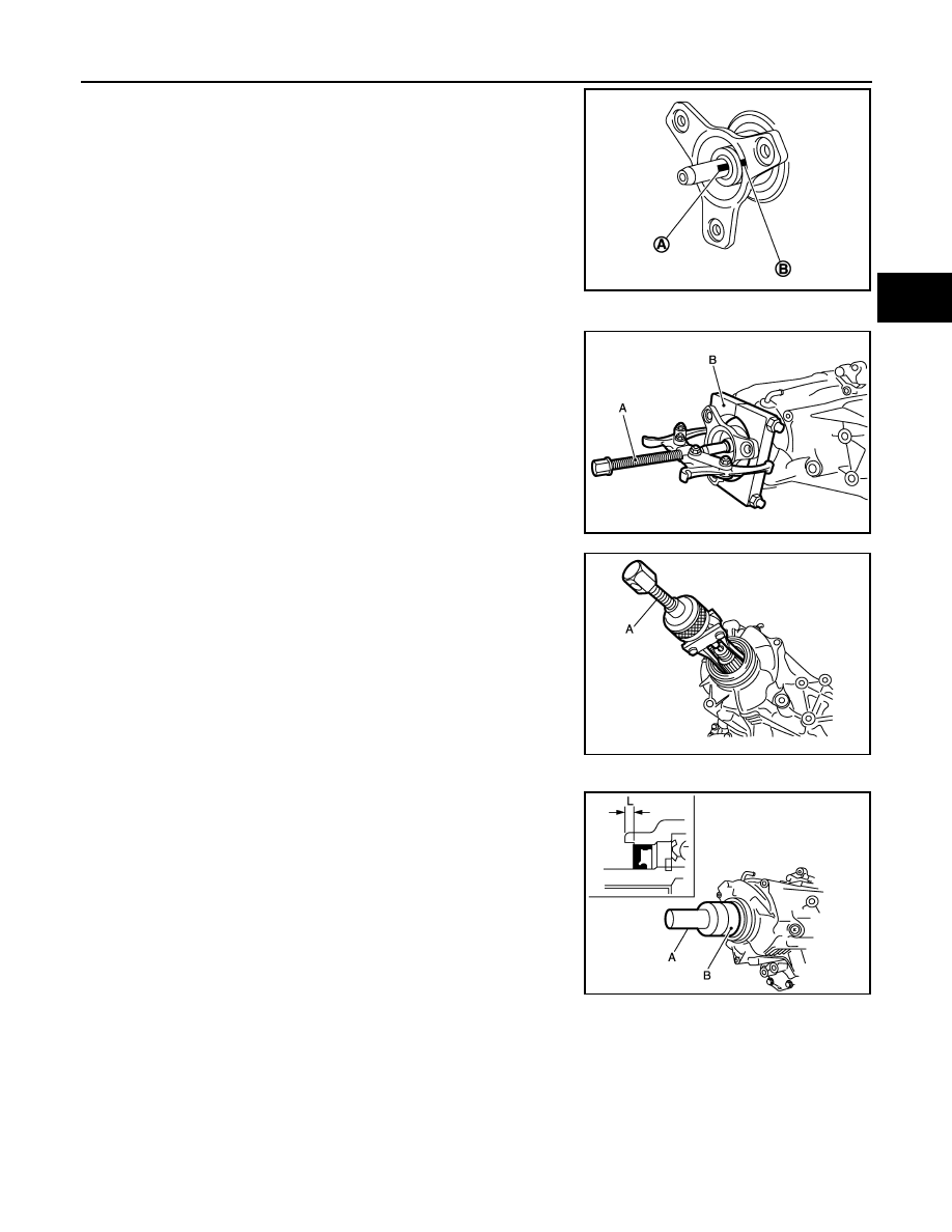
3.
Put a matching mark (A) on the end of the main shaft. The mark
should be in line with the mark (B) on the companion flange.
CAUTION:
For matching mark, use paint. Never damage main shaft.
4.
Remove the companion flange with a puller and a replacer.
CAUTION:
Never damage the companion flange.
5.
Remove the rear oil seal with the puller (A) [SST: KV381054S0
(J-34286)].
CAUTION:
Never damage the rear case.
INSTALLATION
1.
Apply transfer fluid to rear oil seal, install it with the drifts within
the dimension (L) shown as follows.
CAUTION:
• Never reuse rear oil seal.
• Apply petroleum jelly to oil seal lip.
• When installing, never incline rear oil seal.
JPDIE0104ZZ
A
: Puller (commercial service tool)
B
: Replacer (commercial service tool)
JPDIE0127ZZ
JPDIE0132ZZ
A
: Drift [SST: ST30720000 (J-25405)]
B
: Drift [SST: KV40104830 (
—
)]
L
: 6.7 – 7.3 mm (0.264 – 0.287 in)
JPDIE0133ZZ