Infiniti FX35, FX50 (S51). Manual - part 558


  Index      Infiniti     Infiniti FX35, FX50 (S51) - service repair manual 2010 year


Search            


Content   ..  556  557  558  559   ..


Infiniti FX35, FX50 (S51). Manual - part 558


TRANSFER ASSEMBLY

DLN-67

< UNIT REMOVAL AND INSTALLATION >

[TRANSFER: ETX13C]

C

E

F

G

H

I

J

K

L

M

A

B

DLN

N

O

P

VK50VE : Exploded View

INFOID:0000000005249115

VK50VE : Removal and Installation

INFOID:0000000005249116

REMOVAL

1.

Remove transmission assembly from the vehicle. Refer to 

EM-196, "Removal and Installation"

.

2.

Remove transfer air breather hose.

3.

Remove rear engine mounting member and engine mounting insulator with power tool. Refer to 

EM-196,

"Exploded View"

.

4.

Support transfer assembly with a jack.

5.

Remove transfer mounting bolts with power tool and separate transfer from transmission.

CAUTION:

Secure transfer assembly and transmission assembly to a jack.

INSTALLATION

Note the following, and install in the reverse order of removal.
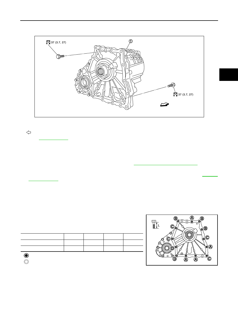
• When installing the transfer to the transmission, install the mount-

ing bolts following the standard below, tighten bolts to the specified
torque.

:Transfer to transmission.

:Transmission to transfer.

• When installing transfer air breather hose, make sure there are no pinched or restricted areas on the transfer

air breather hose caused by bending or winding.

1.

Transfer assembly

: Vehicle front

Refer to 

GI-4, "Components"

 for symbols in the figure.

JPDIE0128GB

Bolt No.

A

B

C

D

Quantity

4

3

4

2

Bolt length “ L ” mm (in)

75 (2.95)

45 (1.77)

40 (1.57)

30 (1.18)

JPDIE0105ZZ

DLN-68

< UNIT REMOVAL AND INSTALLATION >

[TRANSFER: ETX13C]

TRANSFER ASSEMBLY

- Set transfer air breather hose with the paint mark (A) facing

upward.

- Be sure to insert air breather hose (1) of transmission side to air

breather tube until hose end reaches the tube bend R portion. 

- Be sure to insert air breather hose (1) of transfer side to air

breather tube (2) until hose end reaches the tube bend R portion.

- Be sure to fix air breather hose in (A) parts of transmission and

transfer.

• After the installation, check the fluid level, fluid leakage and the A/T

positions. Refer to 

DLN-56, "VQ35HR : Inspection"

.

JPDIE0107ZZ

JSDIA0857ZZ

JPDIE0106ZZ

JSDIA0855ZZ

FRONT CASE AND REAR CASE

DLN-69

< UNIT DISASSEMBLY AND ASSEMBLY >

[TRANSFER: ETX13C]

C

E

F

G

H

I

J

K

L

M

A

B

DLN

N

O

P

UNIT DISASSEMBLY AND ASSEMBLY

FRONT CASE AND REAR CASE

VQ35HR

VQ35HR : Exploded View

INFOID:0000000005249117

1.

Plug

2.

Drive chain

3.

Front drive shaft rear bearing

4.

Front drive shaft

5.

Front drive shaft front bearing

6.

Sprocket

7.

Needle bearing

8.

Main shaft

9.

Oil pump

10. Spacer

11.

Steel ball

12. Snap ring

13. Snap ring

14. Main shaft bearing

15. Front case

16. Main shaft oil seal

17. Front oil seal

18. Spacer

19. Snap ring

20. Circlip

21. Electric controlled coupling

22. Oil cover

23. O-ring

24. Retainer

25. Transfer fluid temperature sensor

26. Baffle plate

27. Spacer

28. Snap ring

29. Dowel pin

30. Rear case

31. Harness bracket

32. Breather tube

33. Filler plug

34. Gasket

35. Drain plug

36. Rear bearing

37. Snap ring

38. Spacer

39. Rear oil seal

JPDIE0200GB

DLN-70

< UNIT DISASSEMBLY AND ASSEMBLY >

[TRANSFER: ETX13C]

FRONT CASE AND REAR CASE

VQ35HR : Disassembly

INFOID:0000000005249118

1.

Remove drain plug and filler plug.

2.

Remove harness brackets.

3.

Remove main shaft oil seal from front case.

CAUTION:

Never damage the front case and main shaft.

4.

Remove front oil seal from front case.

CAUTION:

Never damage the front case and front drive shaft.

5.

Remove self-lock nut.

6.

Put a matching mark (A) on the end of main shaft. The mark
should be in line with the mark (B) on the companion flange.

CAUTION:

For the matching mark, use paint. Never damage main
shaft.

7.

Remove companion flange with a puller (A) (commercial service
tool).

CAUTION:

Never damage the companion flange.

8.

Remove rear oil seal from rear case with the puller (A)
[SST:KV381054S0 (J-34286)].

CAUTION:

Never damage the rear case.

9.

Remove spacer from main shaft.

40. Companion flange

41. Self-lock nut

A.

Oil seal lip

B.

Matching surface

: Apply Genuine Anaerobic Liquid Gasket or equivalent. Refer to 

GI-16, "Recommended Chemical Products and Sealants"

.

: Apply petroleum jelly.

: Apply transfer fluid. Refer to 

MA-12, "Fluids and Lubricants"

.

Refer to 

GI-4, "Components"

 for symbols not described above.

JPDIE0060ZZ

JSDIA0806ZZ

JPDIE0132ZZ


Content   ..  556  557  558  559   ..