Infiniti EX35. Manual - part 318


  Index      Infiniti     Infiniti EX35 - service repair manual 2008 year


Search            


Content   ..  316  317  318  319   ..


Infiniti EX35. Manual - part 318


BR-34

< ON-VEHICLE REPAIR >

FRONT DISC BRAKE

1.

Apply Copper based brake grease to the pad retainers before installing it to the torque member if the pad
retainers has been removed.

CAUTION:

• Securely assemble the pad retainers so that it will not be lifted up from the torque member.
• Never deform the pad retainers.

2.

Apply Copper based brake grease to the mating faces between the shims and the shim covers and install
them to the brake pad.

CAUTION:

Always replace the shims together with the shim covers when replacing the brake pad.

3.

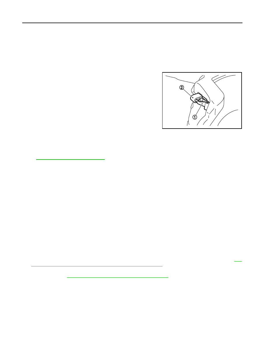
Install the brake pads to the torque member.

CAUTION:

Both inner and outer pads have a pad return system on the
pad retainer. Install pad return lever (1) securely to pad wear
sensor (2).

4.

Install cylinder body to torque member.

CAUTION:

• Never damage the piston boot.
• When replacing brake pad with new one, check a brake

fluid level in the reservoir tank because brake fluid
returns to master cylinder reservoir tank when pressing
piston in.

NOTE:
Use a disc brake piston tool to easily press piston. 

5.

Install the lower sliding pin bolt and tighten it to the specified torque.

6.

Depress the brake pedal several times to check that no drag feel is present for the front disc brake. Refer
to 

BR-34, "BRAKE PAD : Inspection"

.

BRAKE PAD : Inspection

INFOID:0000000003140012

INSPECTION AFTER REMOVAL

Replace the shims and the shim covers if rust is excessively attached.

INSPECTION AFTER INSTALLATION

1.

Check a drag of front disc brake. If any drag is found, follow the procedure described below.

2.

Remove brake pads.

3.

Press the pistons.

CAUTION:

• Never damage the piston boot.
• When replacing a pad with new one, check a brake fluid level in the reservoir tank because brake

fluid returns to master cylinder reservoir tank when pressing piston in.

NOTE:
Use a disc brake piston tool to easily press piston.

4.

Install brake pads.

5.

Depress the brake pedal several times.

6.

Check a drag of front disc brake again. If any drag is found, disassemble the cylinder body. Refer to 

BR-

36, "BRAKE CALIPER ASSEMBLY : Disassembly and Assembly"

7.

Burnish contact surfaces after refinishing or replacing brake pads, or if a soft pedal occurs at very low
mileage. Refer to 

BR-14, "BRAKE PAD : Inspection and Adjustment"

.

BRAKE CALIPER ASSEMBLY

BRAKE CALIPER ASSEMBLY : Exploded View

INFOID:0000000003140017

REMOVAL

JPFIA0027ZZ

FRONT DISC BRAKE

BR-35

< ON-VEHICLE REPAIR >

C

D

E

G

H

I

J

K

L

M

A

B

BR

N

O

P

DISASSEMBLY

BRAKE CALIPER ASSEMBLY : Removal and Installation

INFOID:0000000003140018

REMOVAL

WARNING:

Clean any dust from the brake caliper and brake pads with a vacuum dust collector. Never blow with
compressed air.

1.

Brake caliper assembly

Refer to 

GI-4, "Components"

 for symbols not described on the above.

JPFIA0328GB

1.

Cap

2.

Bleeder valve

3.

Cylinder body

4.

Sliding pin

5.

Sliding pin boot

6.

Bushing

7.

Piston seal

8.

Piston

9.

Piston boot

10.

Torque member

: Apply rubber grease.

: Apply brake fluid.

Refer to 

GI-4, "Components"

 for symbols not described on the above.

JPFIA0329GB

BR-36

< ON-VEHICLE REPAIR >

FRONT DISC BRAKE

CAUTION:

Never depress the brake pedal. Brake fluid may splash while removing the brake hose.
1.

Remove tires with power tool.

2.

Fix the disc rotor using wheel nuts.

3.

Drain brake fluid. Refer to 

BR-10, "Draining"

.

CAUTION:

Never spill or splash brake fluid on the disc rotor.

4.

Remove union bolt and copper washer, and disconnect brake hose from caliper assembly. Refer to 

BR-

20, "FRONT : Exploded View"

.

5.

Remove torque member mounting bolts, and remove brake caliper assembly.

CAUTION:

Never drop brake pad and caliper assembly.

6.

Remove disc rotor.

CAUTION:

• Put matching marks on the wheel hub and bearing assembly and the disc rotor before removing

the disc rotor.

• Never drop disc rotor.

INSTALLATION

WARNING:

Clean any dust from the brake caliper and brake pads with a vacuum dust collector. Never blow with
compressed air.

CAUTION:

Never depress the brake pedal. Brake fluid may splash while removing the brake hose.

1.

Install disc rotor.

CAUTION:

Align the matching marks that have been made during removal when reusing the disc rotor.

2.

Install the brake caliper assembly to the vehicle and tighten the torque member mounting bolts to the
specified torque.

CAUTION:

Never spill or splash any grease and moisture on the brake caliper assembly mounting face,
threads, mounting bolts and washers. Wipe out any grease and moisture.

3.

Install brake hose and copper washers to brake caliper assembly, and tighten union bolts to the specified
torque. Refer to 

BR-20, "FRONT : Exploded View"

.

CAUTION:

Never reuse copper washer.

4.

Refill with new brake fluid and perform the air bleeding. Refer to 

BR-11, "Bleeding Brake System"

.

CAUTION:

• Never reuse drained brake fluid.
• Never spill or splash brake fluid on the disc rotor.

5.

Check a drag of front disc brake. If any drag is found, refer to 

BR-38, "BRAKE CALIPER ASSEMBLY :

Inspection"

.

BRAKE CALIPER ASSEMBLY : Disassembly and Assembly

INFOID:0000000003140019

DISASSEMBLY

NOTE:
Never remove the torque member and pad retainers when disassembling and assembling the cylinder body.

1.

Remove the sliding pin bolt, and remove the cylinder body from the torque member.

CAUTION:

Never drop pads, shims, shim covers and pad retainers from torque member.

2.

Remove brake pads, shims and shim covers. Refer to 

BR-33, "BRAKE PAD : Exploded View"

.

3.

Remove sliding pins and sliding pin boots from torque member.

4.

Remove bushing from sliding pin.

FRONT DISC BRAKE

BR-37

< ON-VEHICLE REPAIR >

C

D

E

G

H

I

J

K

L

M

A

B

BR

N

O

P

5.

Place a wooden block as shown in the figure, and blow air from
union bolt mounting hole to remove pistons and piston boots.

CAUTION:

Never get fingers caught in the pistons.

6.

Remove piston seal from cylinder body using suitable tool.

CAUTION:

Be careful not to damage a cylinder inner wall.

7.

Remove bleeder valve and cap.

ASSEMBLY

1.

Install bleeder valve and cap.

2.

Apply rubber grease to piston seals (1), and install them to cylin-
der body.

CAUTION:

Never reuse piston seals.

3.

Apply rubber grease to piston boots (1). Cover the piston (2) end
with piston boot, and then install cylinder side lip on piston boot
securely into a groove on cylinder body.

CAUTION:

Never reuse piston boots.

BRB0032D

SFIA0141E

JPFIA0032ZZ

JPFIA0033ZZ


Content   ..  316  317  318  319   ..