Infiniti EX35. Manual - part 316


  Index      Infiniti     Infiniti EX35 - service repair manual 2008 year


Search            


Content   ..  314  315  316  317   ..


Infiniti EX35. Manual - part 316


BR-26

< ON-VEHICLE REPAIR >

BRAKE MASTER CYLINDER

• The piston may drop off when pulled out strongly. Never hold the piston. Hold the cylinder body

when handling the master cylinder assembly.

INSTALLATION

CAUTION:

Never spill or splash brake fluid on painted surfaces. Brake fluid may seriously damage paint. Wipe it
off immediately and wash with water if it gets on a painted surface.
Note the following, and install in the reverse order of removal.
• Never depress the brake pedal after the master cylinder assembly is removed.
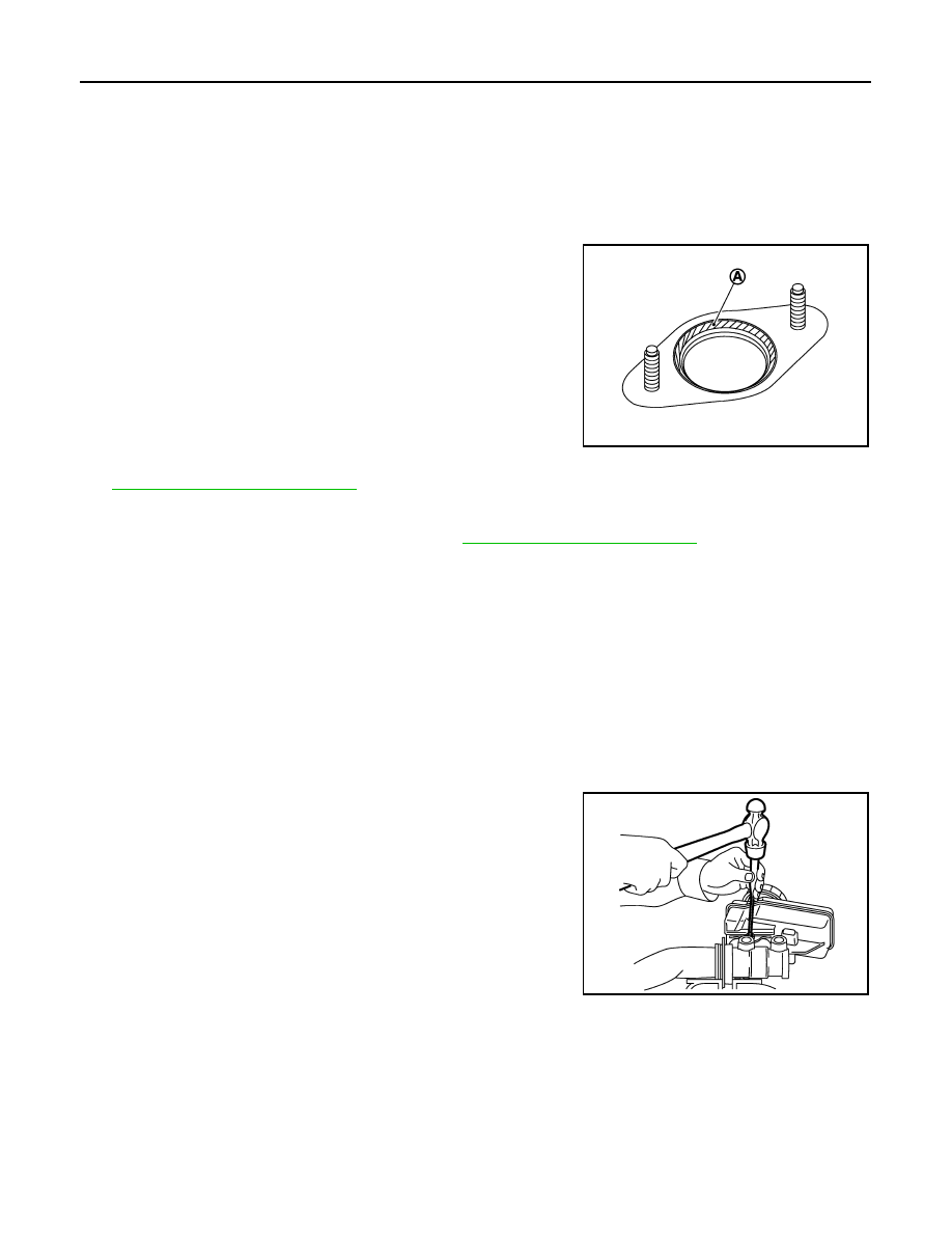
• Apply PBC (Poly Butyl Cuprysil) silicone-based grease to the

brake booster [see (A) in the figure] when installing the master cyl-
inder assembly to the brake booster.

• The piston of the master cylinder assembly is exposed. Never

damage it when handling the master cylinder and check that no dirt
and dust are present on the piston before installation. Clean it with
new brake fluid if necessary.

• The piston may drop off when pulled strongly. Never hold the pis-

ton. Hold the cylinder body when handling the master cylinder
assembly.

• Never reuse the O ring.
• Temporarily tighten the brake tube flare nut to the master cylinder

assembly by hand. Then tighten it to the specified torque with a flare nut crowfoot and torque wrench. Refer
to 

BR-20, "FRONT : Exploded View"

.

CAUTION:

Never scratch the flare nut and the brake tube.

• After installation, perform the air bleeding. Refer to 

BR-11, "Bleeding Brake System"

CAUTION:

Never reuse drained brake fluid.

Disassembly and Assembly

INFOID:0000000003139996

DISASSEMBLY

CAUTION:

• Never disassemble the cylinder body.
• Remove the reservoir tank only when necessary.

1.

Fix the master cylinder assembly to a vise.

CAUTION:

Always set copper plates or cloth between them when fixing the cylinder body to a vise. Never
overtighten the vise.

2.

Remove the reservoir tank mounting pin with a pin punch.

3.

Remove the reservoir tank and grommet from the cylinder body.

CAUTION:

Never drop the removed parts. The parts must not be
reused if they are dropped.

ASSEMBLY

1.

Apply new brake fluid to the grommet and install it to the cylinder body.

CAUTION:

• Never use mineral oil such as gasoline or light oil.
• Never reuse the grommets.

2.

Install the reservoir tank to the cylinder body.

CAUTION:

• Never drop the parts when installing. The parts must not be reused if they are dropped.
• Never reuse the reservoir tank.

JPFIA0013ZZ

JPFIA0015ZZ

BRAKE MASTER CYLINDER

BR-27

< ON-VEHICLE REPAIR >

C

D

E

G

H

I

J

K

L

M

A

B

BR

N

O

P

3.

Fix the cylinder body to a vise.

CAUTION:

• Place the reservoir tank with the chamfered pin hole (

)

facing up.

• Always set copper plates or cloth between them when fix-

ing the cylinder body to a vise. Never overtighten the vise.

4.

Tilt the reservoir tank so that a mounting pin can be inserted.
Insert a mounting pin. Return the reservoir tank to the horizontal
position. Insert another mounting pin into the pin hole on the
opposite side in the same manner after the mounting pin passes
through the cylinder body pin hole.

CAUTION:

Never reuse the mounting pins.

Inspection

INFOID:0000000003139997

INSPECTION AFTER INSTALLATION

Fluid Leak

Check for brake fluid leakage from the cylinder body-to-brake booster mounting face, reservoir tank mounting
face and brake tube connections.

JPFIA0016ZZ

JPFIA0015ZZ

BR-28

< ON-VEHICLE REPAIR >

BRAKE BOOSTER

BRAKE BOOSTER

Exploded View

INFOID:0000000003140001

Removal and installation

INFOID:0000000003140002

REMOVAL

1.

Remove master cylinder cover.

2.

Remove cowl top cover. Refer to 

EXT-22, "Exploded View"

.

3.

Remove brake master cylinder assembly. Refer to 

BR-25, "Exploded View"

.

CAUTION:

• Depress the brake pedal several times to release the vacuum pressure from the brake booster.

Then remove the master cylinder assembly.

• Never depress the brake pedal after the master cylinder assembly is removed.
• The piston of the master cylinder assembly is exposed. Never damage it when removing the

master cylinder.

• The piston may drop off when pulled out strongly. Never hold the piston. Hold the cylinder body

when handling the master cylinder assembly.

4.

Remove vacuum hose from brake booster. Refer to 

BR-31, "Exploded View"

.

5.

Remove snap pin (1) and clevis pin (2) from inside vehicle.

6.

Remove nuts on brake booster and brake pedal assembly. Refer
to 

BR-18, "Exploded View"

.

CAUTION:

Hold the brake booster so as to avoid dropping out.

7.

Remove brake booster from dash panel in engine room side.

CAUTION:

Never deform or bend the brake tubes.
NOTE:
If removing brake booster is difficult, remove clevis from brake
booster.

INSTALLATION

Note the following, and install in the reverse order of removal.
• Be careful not to damage brake booster stud bolt threads. If brake booster is tilted during installation, the

dash panel may damage the threads.

1.

Master cylinder assembly

2.

Brake booster

3.

Lock nut

4.

Clevis

5.

Gasket

Refer to 

GI-4, "Components"

 for symbols in the figure.

JPFIA0326GB

JPFIA0019ZZ

BRAKE BOOSTER

BR-29

< ON-VEHICLE REPAIR >

C

D

E

G

H

I

J

K

L

M

A

B

BR

N

O

P

•  Never deform or bend the brake tubes when installing the brake booster.
• Always use a new gasket between the brake booster and the dash panel.
• Replace the clevis pin if it is damaged. Refer to 

BR-19, "Inspection and Adjustment"

.

• Install the brake pedal assembly and brake booster mounting nuts, and tighten it to the specified torque.
• After installation, perform the air bleeding. Refer to 

BR-11, "Bleeding Brake System"

.

CAUTION:

Never reuse drained brake fluid.

Inspection and Adjustment

INFOID:0000000003140003

INSPECTION AFTER REMOVAL

Input Rod Length Inspection

1.

Loosen the lock nut (1) and adjust the input rod (2) to the speci-
fied length (A).

2.

Tighten the lock nut to the specified torque.

INSPECTION AFTER INSTALLATION

Operation

Depress the brake pedal several times at 5-second intervals with the
engine stopped. Start the engine with the brake pedal fully
depressed. Check that the clearance between brake pedal and dash
lower pane decreases.
NOTE:
A slight impact with a small click may be felt on the pedal when the
brake pedal is fully depressed. This is a normal phenomenon due to
the brake system operation.

Air Tight

• Idle the engine for 1 minute to apply vacuum to the brake booster,

and stop the engine. Then depress the brake pedal several times
at 5-second intervals until the accumulated vacuum is released to
atmospheric pressure. Check that the clearance between brake
pedal and dash lower panel gradually increases (A 

 B 

 C) each

time the brake pedal is depressed when performing this operation.

Standard

A

: Refer to 

BR-46, "Brake Booster"

.

JPFIA0238ZZ

BRA0037D

JPFIA0043ZZ


Content   ..  314  315  316  317   ..