Honda Odyssey 2004. Manual - part 550


  Index      Honda     Honda Odyssey 2004 - service repair manual 2004 year


Search            


Content   ..  548  549  550  551   ..


Honda Odyssey 2004. Manual - part 550


*02

07

YES

NO

23-142

SRS

DTC Troubleshooting (cont’d)

C851

A

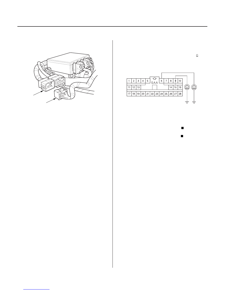
SRS MAIN HARNESS 28P CONNECTOR

20. Disconnect the SRS main harness 28P connector

(A) from the SRS floor harness 28P connector C851.

21. Check resistance between the No. 6 terminal of the

SRS main harness 28P connector and body ground,
and between the No. 15 terminal and body ground.
There should be an open circuit, or at least 1 M

.

Replace the SRS floor harness.

Replace the SRS main harness.

Wire side of female terminals

Is the r esistance as specif ied?

03/07/29 10:34:53 61S0X050_230_0142

S0X4AZ3K79100081051FAAT31

S0X4AZ3K79100081101FAAT10

’02 Model

DTC 5-1, 5-2, 5-4, 5-8, 6-3, 6-4, 6-7, 6-8, 7-1,
7-2, 7-3, 8-1, 8-2, 8-3, 8-4, 8-5, 8-6, 9-1, 9-2:

’02 Model

DTC 10-1, 10-2, 10-3, 10-4, 10-5, 10-6, 10-7:

YES

NO

23-143

23-143

Internal Failure of the SRS Unit

Airbags, Side Airbags and/or Seat Belt
Tensioners Deployed

NOTE: Before troubleshooting any of these DTCs, check
the battery/system voltage. If the voltage is low, repair
the charging system or replace the battery before
troubleshooting the SRS. If the battery/system voltage
is now OK, ask the customer if the battery ever went
dead.

1. Erase the DTC memory (see page 23-38).

2. Turn the ignition switch ON (II), and check that the

SRS indicator comes on for about 6 seconds and
then goes off.

Replace the SRS unit (see page 23-382).

Intermittent failure, system is OK at this time.

Go to Troubleshooting Intermittent Failures (see
page 23-39).

The SRS unit must be replaced after any airbags and/or
tensioners have deployed (see page 23-382).

Does the SRS indicator stay on?

03/07/29 10:34:53 61S0X050_230_0143

S0X4AZ3K79100081131FAAT00

S0X4AZ3K79100081141FAAT00

’02 Model

DTC 13-1, 13-2:

’02 Model

DTC 14-1, 14-2:

YES

NO

YES

NO

23-144

23-144

SRS

DTC Troubleshooting (cont’d)

Internal Failure of the Driver’s

Side Impact Sensor

Internal Failure of the Front

Passenger’s Side Impact Sensor

1. Erase the DTC memory (see page 23-38).

2. Turn the ignition switch ON (II), and check that the

SRS indicator comes on for about 6 seconds and
then goes off.

Replace the driver’s side impact sensor (see

page 23-385).

Intermittent failure, system is OK at this time.

Go to Troubleshooting Intermittent Failures (see
page 23-39).

1. Erase the DTC memory (see page 23-38).

2. Turn the ignition switch ON (II), and check that the

SRS indicator comes on for about 6 seconds and
then goes off.

Replace the front passenger’s side impact

sensor (see page 23-385).

Intermittent failure, system is OK at this time.

Go to Troubleshooting Intermittent Failures (see
page 23-39).

Does the SRS indicator stay on?

Does the SRS indicator stay on?

03/07/29 10:34:53 61S0X050_230_0144

01

01

S0X4AZ3K79100081093FAAT00

’02 Model

DTC 9-3:

YES

NO

YES

NO

23-145

B

A

DRIVER’S SEAT BELT BUCKLE SWITCH
3P CONNECTOR

BLU/RED

BLK

BLK

RED/BLU

Faulty Driver’s Seat Belt Buckle

Switch

1. Erase the DTC memory (see page 23-38).

2. Turn the ignition switch ON (II), then buckle and

unbuckle the driver’s seat belt several times.

3. Read the DTC (see page 23-35).

Go to step 4.

Intermittent failure, system is OK at this time.

Go to Troubleshooting Intermittent Failures (see
page 23-39).

4. Turn the ignition switch OFF.

5. Disconnect the left side wire harness 3P connector

(A) from the driver’s seat belt buckle switch 3P
connector (B).

6. Buckle the driver’s seat belt.

• Check resistance between the No. 1 and No. 3

terminals of the driver’s seat belt buckle switch
3P connector. There should be 0

1

.

• Check resistance between the No. 1 and No. 2

terminals of the same connector. There should
be an open circuit, or at least 1 M

.

Go to step 7.

Replace the driver’s seat belt buckle assembly,

and clear the DTC.

(cont’d)

Terminal side of male terminals

Terminal side of male terminals

Is DT C 9-3 indicated?

Ar e the r esistance r eadings as specif ied?

03/07/29 10:34:54 61S0X050_230_0145


Content   ..  548  549  550  551   ..