Honda Odyssey 2004. Manual - part 551


  Index      Honda     Honda Odyssey 2004 - service repair manual 2004 year


Search            


Content   ..  549  550  551  552   ..


Honda Odyssey 2004. Manual - part 551


*01

02

03

YES

NO

YES

NO

23-146

SRS

DTC Troubleshooting (cont’d)

BLK

BLU/RED

BLK

RED/BLU

DRIVER’S SEAT BELT BUCKLE SWITCH
3P CONNECTOR

LEFT SIDE WIRE HARNESS 3P CONNECTOR

BLK

C

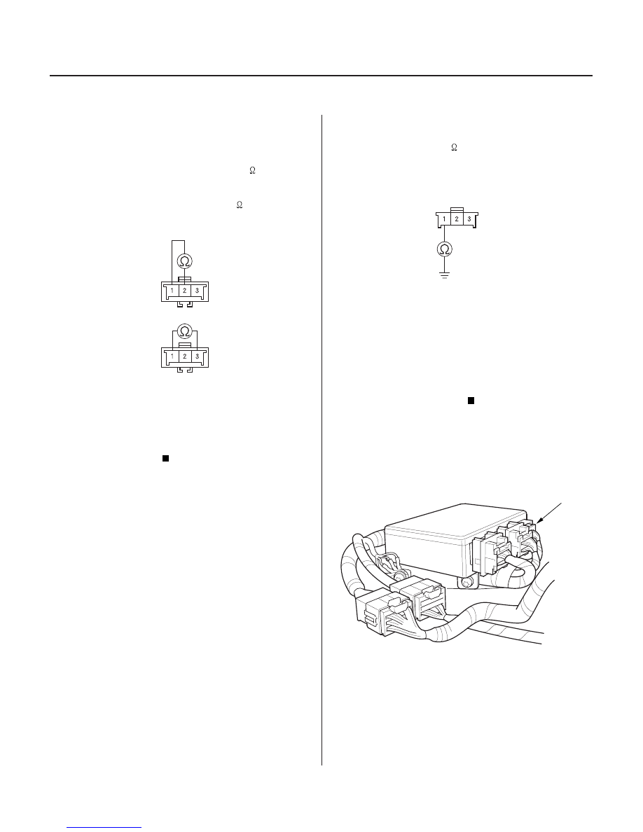
7. Unbuckle the driver’s seat belt.

• Check resistance between the No. 1 and No. 2

terminals of the driver’s seat belt buckle switch
3P connector. There should be 0

1

.

• Check resistance between the No. 1 and No. 3

terminals of the same connector. There should
be an open circuit, or at least 1 M

.

Go to step 8.

Replace the driver’s seat belt buckle assembly,

and clear the DTC.

8. Check resistance between the No. 1 terminal of the

left side wire harness connector and body ground.
There should be 0

1

.

Go to step 9.

Open in the left side wire harness or poor

ground connection at G551. If G551 is OK, replace
the left side wire harness.

9. Disconnect the negative cable from the battery.

10. Disconnect SRS unit connector C (8P) from the SRS

unit, dashboard harness connector C (16P) from the
gauge assembly, and the driver’s multiplex control
unit from the driver’s under-dash fuse/relay box.

Terminal side of male terminals

Terminal side of male terminals

Wire side of female terminals

Is the r esistance as specif ied?

Is the r esistance as specif ied?

03/07/29 10:34:55 61S0X050_230_0146

*06

05

06

07

YES

NO

YES

NO

YES

NO

YES

NO

23-147

LEFT SIDE WIRE HARNESS 3P CONNECTOR

RED/BLU

LEFT SIDE WIRE HARNESS 3P CONNECTOR

BLU/RED

LEFT SIDE WIRE HARNESS
3P CONNECTOR

BLU/RED

SRS UNIT CONNECTOR C (8P)

BLU/RED

LEFT SIDE WIRE HARNESS
3P CONNECTOR

SRS UNIT CONNECTOR C (8P)

RED/BLU

RED/BLU

11. Check resistance between the No. 2 terminal of the

left side wire harness 3P connector and body
ground. There should be an open circuit, or at least
1 M

.

Go to step 12.

Go to step 15.

12. Check resistance between the No. 3 terminal of the

left side wire harness 3P connector and body
ground. There should be an open circuit, or at least
1 M

.

Go to step 13.

Go to step 17.

13. Check resistance between the No. 8 terminal of

SRS unit connector C (8P) and the No. 3 terminal of
the left side wire harness 3P connector. There
should be 0

1

.

Go to step 14.

Go to step 19.

14. Check resistance between the No. 4 terminal of

SRS unit connector C (8P) and the No. 2 terminal of
the left side wire harness 3P connector. There
should be 0

1

.

Replace the SRS unit (see page 23-382).

Go to step 21.

(cont’d)

Wire side of female terminals

Wire side of female terminals

Wire side of female terminals

Wire side of female terminals

Is the r esistance as specif ied?

Is the r esistance as specif ied?

Is the r esistance as specif ied?

Is the r esistance as specif ied?

03/07/29 10:34:55 61S0X050_230_0147

*02

09

*03

11

YES

NO

YES

NO

23-148

SRS

DTC Troubleshooting (cont’d)

A

C503

LEFT SIDE WIRE HARNESS 3P CONNECTOR

RED/BLU

A

C503

LEFT SIDE WIRE HARNESS 3P CONNECTOR

RED/BLU

15. Disconnect the SRS main harness 8P connector (A)

from the dashboard wire harness 8P connector
C503.

16. Check resistance between the No. 2 terminal of the

left side wire harness 3P connector and body
ground. There should be an open circuit, or at least
1 M

.

Short to ground in the SRS main harness or

SRS floor harness; replace the floor harness. If the
problem is still present; replace the SRS floor
harness.

Short to ground in the left side wire harness

or dashboard wire harness; replace the faulty
harness.

17. Disconnect the SRS main harness 8P connector (A)

from the dashboard wire harness 8P connector
C503.

18. Check resistance between the No. 3 terminal of the

left side wire harness 3P connector and body
ground. There should be an open circuit, or at least
1 M

.

Short to ground in the SRS main harness or

SRS floor harness; replace the floor harness. If the
problem is still present; replace the SRS floor
harness.

Short to ground in the left side wire harness

or dashboard wire harness; replace the faulty
harness.

Wire side of female terminals

Wire side of female terminals

Is the r esistance as specif ied?

Is the r esistance as specif ied?

03/07/29 10:34:56 61S0X050_230_0148

*04

13

*05

15

YES

NO

YES

NO

23-149

A

C503

SRS UNIT CONNECTOR C (8P)

BLU/RED

BLU/RED

SRS MAIN HARNESS
8P CONNECTOR

A

C503

SRS UNIT CONNECTOR C (8P)

RED/BLU

RED/BLU

SRS MAIN HARNESS
8P CONNECTOR

19. Disconnect the SRS main harness 8P connector (A)

from the dashboard wire harness 8P connector
C503.

20. Check resistance between the No. 8 terminal of

SRS unit connector C (8P) and the No. 8 terminal of
the SRS main harness 8P connector. There should
be 0

1

.

Open in the left side wire harness or

dashboard wire harness; replace the faulty
harness.

Open in the SRS main harness or SRS floor

harness; replace the SRS floor harness. If the
problem is still present, replace the SRS main
harness.

21. Disconnect the SRS main harness 8P connector (A)

from the dashboard wire harness 8P connector
C503.

22. Check resistance between the No. 4 terminal of

SRS unit connector C (8P) and the No. 7 terminal of
the SRS main harness 8P connector. There should
be 0

1

.

Open in the left side wire harness or

dashboard wire harness; replace the faulty
harness.

Open in the SRS main harness or SRS floor

harness; replace the SRS floor harness. If the
problem is still present, replace the SRS main
harness.

Wire side of female terminals

Wire side of female terminals

Is the r esistance as specif ied?

Is the r esistance as specif ied?

03/07/29 10:34:57 61S0X050_230_0149


Content   ..  549  550  551  552   ..