Honda Odyssey 2004. Manual - part 175


  Index      Honda     Honda Odyssey 2004 - service repair manual 2004 year


Search            


Content   ..  173  174  175  176   ..


Honda Odyssey 2004. Manual - part 175


*01

*02

*03

S0X4AA2K77100091773FAAT00

1999-2000 Models

DTC P1773:

YES

NO

YES

NO

YES

NO

14-94

Automatic Transmission

DTC Troubleshooting (cont’d)

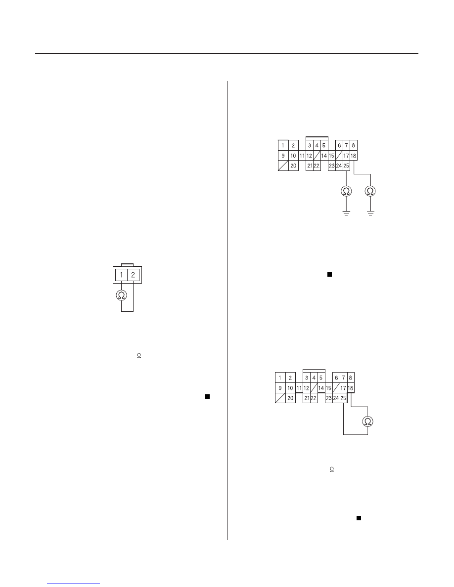
A/T CLUTCH PRESSURE CONTROL
SOLENOID VALVE B CONNECTOR

PCM CONNECTOR B (25P)

LS BM (GRN)

LS BP (ORN)

PCM CONNECTOR B (25P)

LS BM (GRN)

LS BP (ORN)

Problem in A/T Clutch Pressure

Control Solenoid Valve B Circuit

NOTE:

• Record all freeze data and review General

Troubleshooting Information (see page 14-3) before
you troubleshoot.

• This code is caused by an electrical circuit problem

and cannot be caused by a mechanical problem in the
transmission.

1. Disconnect the 2P connector from A/T clutch

pressure control solenoid valve B.

2. Measure A/T clutch pressure control solenoid

resistance at the solenoid valve connector.

Go to step 3.

Replace the A/T clutch pressure control

solenoid valve A/B assembly (see page 14-133).

3. Disconnect the B (25P) connector from the PCM.

4. Check for continuity between body ground and the

B18 terminal and the B25 terminal individually.

Repair short to ground in the wires between

the B18 and B25 terminals and A/T clutch pressure
control solenoid valve B.

Go to step 5.

5. Connect the A/T clutch pressure control solenoid

valve B connector.

6. Measure the resistance between the B18 and B25

terminals.

Go to step 7.

Repair loose terminal or open in the wires

between the B18 and B25 terminals and A/T clutch
pressure control solenoid valve B.

Terminal side of male terminals

Wire side of female terminals

Wire side of female terminals

Is the r esistance about 5

?

Is ther e continuity?

Is the r esistance about 5

?

03/07/29 09:31:14 61S0X050_140_0097

01

*04

YES

NO

YES

NO

14-95

PCM CONNECTORS

B (25P)

LG1 (BRN/BLK)

LG2 (BRN/BLK)

D (16P)

VB SOL (BLK/YEL)

PCM CONNECTOR B (25P)

LG1 (BRN/BLK)

LG2 (BRN/BLK)

7. Disconnect the D (16P) connector from the PCM.

8. Turn the ignition switch ON (II).

9. Measure the voltage between the D5 and B20 or

B22 terminals.

Go to step 10.

Check for blown No. 6 (15A) fuse in the

driver’s under-dash fuse/relay box. If the fuse is OK,
repair open in the wire between the D5 terminal
and the driver’s under-dash fuse/relay box.

10. Turn the ignition switch OFF.

11. Check for continuity between the B20 and B22

terminals and body ground individually.

Check for loose terminal fit in the PCM

connectors. If necessary, substitute a known-good
PCM and recheck.

Repair open in the wire between the B2, B10,

B20, and B22 terminals and ground (G101), or
repair poor ground (G101).

Wire side of female terminals

Wire side of female terminals

Is ther e batter y voltage?

Is ther e continuity?

03/07/29 09:31:15 61S0X050_140_0098

*01

01

02

S0X4AA3K77100090715FAAT00

2001 Model

DTC P0715:

YES

NO

YES

NO

YES

NO

YES

NO

14-96

Automatic Transmission

DTC Troubleshooting (cont’d)

MAINSHAFT SPEED SENSOR CONNECTOR

PCM CONNECTOR C (22P)

NM SG (WHT)

NM (RED)

PCM CONNECTOR C (22P)

NM SG (WHT)

NM (RED)

Problem in Mainshaft Speed

Sensor Circuit

NOTE: Record all freeze data and review General
Troubleshooting Information (see page 14-3) before
you troubleshoot.

Code P0715 (code 15) on the PCM doesn’t always mean
there’s an electrical problem in the mainshaft or
countershaft speed sensor circuit; code P0715 (code 15)
may also indicate a mechanical problem in the
transmission. Any problem causing irregular
countershaft to mainshaft speed difference can cause
this code.

1. Check the mainshaft and countershaft speed

sensor installation.

Go to step 2.

Reinstall and recheck.

2. Disconnect the mainshaft speed sensor connector

(2P).

3. Measure the mainshaft speed sensor resistance at

the sensor connector.

Go to step 4.

Replace the mainshaft speed sensor (see

page 14-134).

4. Disconnect PCM connector C (22P).

5. Check for continuity between PCM connector

terminal C6 and body ground, and between
terminal C7 and body ground.

Repair short in the wires between PCM

connector terminals C6 and C7, and the mainshaft
speed sensor.

Go to step 6.

6. Connect the mainshaft speed sensor connector.

7. Measure the resistance between PCM connector

terminals C6 and C7.

Run the Electrical Troubleshooting Flowchart

for code P0720 (code 9). Check for loose terminal fit
in the PCM connectors. If necessary, substitute a
known-good PCM and recheck.

Go to step 8.

Terminal side of male terminals

Wire side of female terminals

Wire side of female terminals

Ar e the mainshaf t and the counter shaf t speed
sensor s installed pr oper ly?

Is ther e 400

600

?

Is ther e continuity?

Is ther e 400

600

?

03/07/29 09:31:15 61S0X050_140_0099

03

04

YES

NO

YES

NO

14-97

PCM CONNECTOR C (22P)

NM (RED)

MAINSHAFT SPEED
SENSOR CONNECTOR

RED

PCM CONNECTOR C (22P)

NM SG (WHT)

MAINSHAFT SPEED
SENSOR CONNECTOR

WHT

8. Disconnect the mainshaft speed sensor connector

(2P).

9. Check for continuity between PCM connector

terminal C7 and the No. 1 terminal of the mainshaft
speed sensor connector.

Go to step 10.

Repair open in the wire between PCM

connector terminal C7 and the mainshaft speed
sensor.

10. Check for continuity between PCM connector

terminal C6 and the No. 2 terminal of the mainshaft
speed sensor connector.

Check for loose terminal fit in the PCM

connectors. If necessary, substitute a known-good
PCM and recheck.

Repair open in the wire between PCM

connector terminal C6 and the mainshaft speed
sensor.

Wire side of female terminals

Wire side of female terminals

Is ther e continuity?

Is ther e continuity?

03/07/29 09:31:16 61S0X050_140_0100


Content   ..  173  174  175  176   ..