Honda Odyssey 2004. Manual - part 174
−
−
−
−
−
−
−
01
02
*01
S0X4AA2K77100091753FAAT00
1999-2000 Models
DTC P1753:
YES
NO
YES
NO
YES
NO
14-90
Automatic Transmission
DTC Troubleshooting (cont’d)
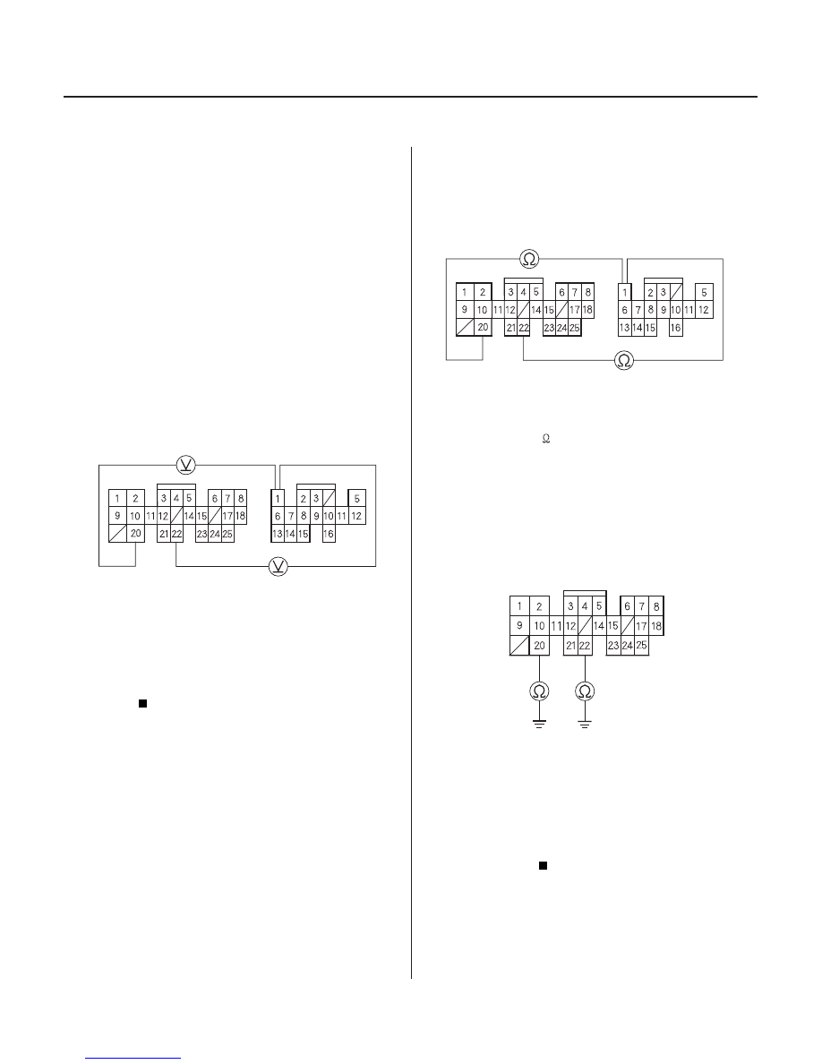
PCM CONNECTORS
B (25P)
LC (YEL)
LG1 (BRN/BLK) LG2 (BRN/BLK)
D (16P)
PCM CONNECTORS
B (25P)
LC (YEL)
LG1 (BRN/BLK)
LG2 (BRN/BLK)
D (16P)
PCM CONNECTOR B (25P)
LG1 (BRN/BLK)
LG2 (BRN/BLK)
Problem in Lock-up Control
Solenoid Valve Circuit
NOTE: Record all freeze data and review General
Troubleshooting Information (see page 14-3) before
you troubleshoot.
1. Turn the ignition switch OFF.
2. Disconnect the B (25P) and D (16P) connectors from
the PCM.
3. Turn the ignition switch ON (II).
4. Measure the voltage between the D1 and B20 or
B22 terminals.
Repair short to power in the wire between
the D1 terminal and the lock-up control solenoid
valve.
Go to step 5.
5. Turn the ignition switch OFF.
6. Measure the resistance between the D1 and B20 or
B22 terminals.
Go to step 11.
Go to step 7.
7. Check for continuity between the B20 and B22
terminals and body ground.
Go to step 8.
Repair open in the wires between the B20 and
B22 terminals and ground (G101), or repair poor
ground (G101).
Wire side of female terminals
Wire side of female terminals
Wire side of female terminals
Is ther e voltage?
Is ther e 12
25
?
Is ther e continuity?
03/07/29 09:31:12 61S0X050_140_0093