Honda Odyssey 2004. Manual - part 176


  Index      Honda     Honda Odyssey 2004 - service repair manual 2004 year


Search            


Content   ..  174  175  176  177   ..


Honda Odyssey 2004. Manual - part 176


*01

01

02

S0X4AA3K77100090720FAAT00

2001 Model

DTC P0720:

YES

NO

YES

NO

YES

NO

YES

NO

14-98

Automatic Transmission

DTC Troubleshooting (cont’d)

COUNTERSHAFT SPEED SENSOR CONNECTOR

NC (BLU)

NC SG (GRN)

PCM CONNECTOR C (22P)

NC (BLU)

NC SG (GRN)

PCM CONNECTOR C (22P)

Problem in Countershaft Speed

Sensor Circuit

NOTE:

• Record all freeze data and review General

Troubleshooting Information (see page 14-3) before
you troubleshoot.

• This code is caused by an electrical circuit problem

and cannot be caused by a mechanical problem in the
transmission.

1. Check the countershaft speed sensor installation.

Go to step 2.

Reinstall and recheck.

2. Disconnect the countershaft speed sensor

connector (2P).

3. Measure the countershaft speed sensor resistance

at the sensor connector.

Go to step 4.

Replace the countershaft speed sensor (see

page 14-134).

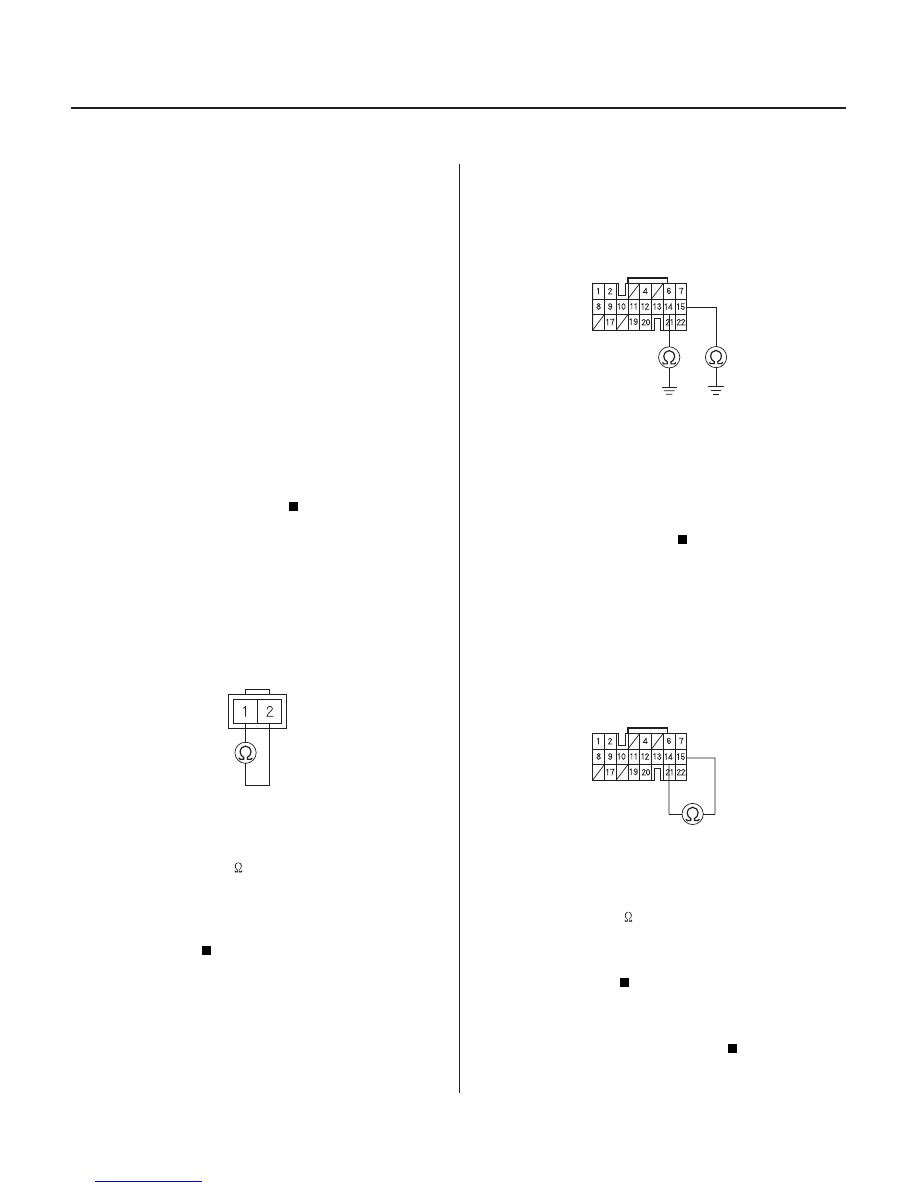
4. Disconnect PCM connector C (22P).

5. Check for continuity between PCM connector

terminal C14 and body ground, and between
terminal C15 and body ground.

Repair short to ground in the wires between

PCM connector terminals C14 and C15, and the
countershaft speed sensor.

Go to step 6.

6. Connect the countershaft speed sensor connector.

7. Measure the resistance between PCM connector

terminals C14 and C15.

Check for loose terminal fit in the PCM

connectors. If necessary, substitute a known-good
PCM and recheck.

Repair loose terminal or open in the wires

between PCM connector terminals C14 and C15,
and the countershaft speed sensor.

Terminal side of male terminals

Wire side of female terminals

Wire side of female terminals

Is the counter shaf t speed sensor installed
pr oper ly?

Is ther e 400

600

?

Is ther e continuity?

Is ther e 400

600

?

03/07/29 09:32:18 61S0X050_140_0101

S0X4AA3K77100090730FAAT00

2001 Model

DTC P0730:

YES

NO

YES

NO

YES

NO

14-99

Problem in Shift Control System

NOTE:

• Record all freeze data and review General

Troubleshooting Information (see page 14-3) before
you troubleshoot.

• Keep replacement solenoid valves on hand:

– Torque converter clutch solenoid valve-shift

solenoid valve A

– Shift solenoid valves B and C
– A/T clutch pressure control solenoid valves A and B

1. Check whether the scan tool or the HDS indicates

another code.

Perform the Troubleshooting Flowchart for

the indicated Code(s). Recheck for code P0730 after
troubleshooting.

Go to step 2.

NOTE: Do not continue with this troubleshooting
until the causes of any other DTCs have been
corrected.

2. Measure the 1st, 2nd, 3rd, and 4th clutch pressure

(see page 14-128).

Go to step 3.

Replace the transmission.

3. Replace the shift solenoid, torque converter clutch

solenoid and A/T clutch pressure control solenoid
set:

• Refer to Torque Converter Clutch Solenoid Valve-

Shift Solenoid Valve A Replacement (see page
14-130).

• Refer to Shift Solenoid Valves B and C

Replacement (see page 14-131).

• Refer to A/T Clutch Pressure Control Solenoid

Valves A and B Replacement (see page 14-133).

4. Clear the DTC with the scan tool or the HDS.

5. Drive the vehicle at speeds over 12 mph (20 km/h)

in 1st, 2nd, 3rd, and 4th gear in D4 position for
more than 30 seconds.

6. Recheck for code P0730.

Replace the transmission.

The system is OK at this time.

Does the scan tool or the HDS indicate another
code?

Is each clutch pr essur e within the ser vice limit?

Does the scan tool or the HDS indicate code
P07 30?

03/07/29 09:32:19 61S0X050_140_0102

S0X4AA3K77100090740FAAT00

2001 Model

DTC P0740:

YES

NO

YES

NO

YES

NO

14-100

Automatic Transmission

DTC Troubleshooting (cont’d)

Problem in Lock-up Control

System

NOTE:

• Record all freeze data and review General

Troubleshooting Information (see page 14-3) before
you troubleshoot.

• Keep replacement solenoid valves on hand:

– Torque converter clutch solenoid valve-shift

solenoid valve A

– A/T clutch pressure control solenoid valves A and B

1. Check whether the scan tool or the HDS indicates

another code.

Perform the Troubleshooting Flowchart for

the indicated Code(s). Recheck for code P0740 after
troubleshooting.

Go to step 2.

NOTE: Do not continue with this troubleshooting
until the causes of any other DTCs have been
corrected.

2. Measure the line pressure (see page 14-128).

Go to step 3.

Replace the transmission.

3. Replace the torque converter clutch solenoid and

A/T clutch pressure control solenoid valve set:

• Refer to Torque Converter Clutch Solenoid Valve-

Shift Solenoid Valve A Replacement (see page
14-130).

• Refer to A/T Clutch Pressure Control Solenoid

Valves A and B Replacement (see page 14-133).

4. Clear the DTC with the scan tool or the HDS.

5. Using the scan tool, check to be sure that the

engine coolant temperature is 176°F (80°C) or
above.

6. Drive the vehicle under the same conditions as

those indicated by the freeze data for more than 1
minute, or drive the vehicle at 55 mph (88 km/h)
with TPS voltage 0.8 V for more than 1 minute.

7. Recheck for code P0740.

Inspect the O-ring on the torque converter. If

the O-ring is missing, replace the O-ring. If the O-
ring is damaged or OK, replace the transmission
and torque converter.

The system is OK at this time.

Does the scan tool or the HDS indicate another
code?

Is the line pr essur e within the ser vice limit?

Does the scan tool or the HDS indicate code
P07 40?

03/07/29 09:32:19 61S0X050_140_0103

01

02

03

S0X4AA3K77100090753FAAT00

2001 Model

DTC P0753:

YES

NO

YES

NO

YES

NO

14-101

LG2 (BRN/BLK)

A (31P)

C (22P)

LG1 (BRN/BLK)

SH A (BLU/YEL)

PCM CONNECTORS

LG2 (BRN/BLK)

A (31P)

C (22P)

LG1 (BRN/BLK)

SH A (BLU/YEL)

PCM CONNECTORS

LG1 (BRN/BLK)

LG2 (BRN/BLK)

PCM CONNECTOR A (31P)

Problem in Shift Solenoid Valve

A Circuit

NOTE:

• Record all freeze data and review General

Troubleshooting Information (see page 14-3) before
you troubleshoot.

• This code is caused by an electrical circuit problem

and cannot be caused by a mechanical problem in the
transmission.

1. Turn the ignition switch OFF.

2. Disconnect PCM connectors A (31P) and C (22P).

3. Turn the ignition switch ON (II).

4. Measure the voltage between PCM connector

terminals C2 and A25 or A26.

Repair short to power in the wire between

PCM connector terminal C2 and the shift solenoid
valve A.

Go to step 5.

5. Turn the ignition switch OFF.

6. Measure the resistance between PCM connector

terminals C2 and A25 or A26.

Go to step 11.

Go to step 7.

7. Check for continuity between PCM connector

terminal A25 and body ground, and between
terminal A26 and body ground.

Go to step 8.

Repair open in the wires between PCM

connector terminals A25 and A26, and ground
(G101), or repair poor ground (G101).

(cont’d)

Wire side of female terminals

Wire side of female terminals

Wire side of female terminals

Is ther e voltage?

Is the r esistance 12

25

?

Is ther e continuity?

03/07/29 09:32:20 61S0X050_140_0104


Content   ..  174  175  176  177   ..