Honda Odyssey 2004. Manual - part 54


  Index      Honda     Honda Odyssey 2004 - service repair manual 2004 year


Search            


Content   ..  52  53  54  55   ..


Honda Odyssey 2004. Manual - part 54


*02

*03

*04

FRONT:

REAR:

6-56

Cylinder Head

Cylinder Head Installation (cont’d)

B

A

B

A

A

B

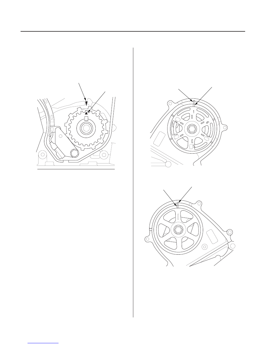
4. Clean the timing belt drive pulley.

5. Set the timing belt drive pulley to top dead center

(TDC) by aligning the TDC mark (A) on the tooth of
the timing belt drive pulley with the pointer (B) on
the oil pump.

6. Clean the camshaft pulleys. Set the camshaft

pulleys to TDC by aligning the TDC marks (A) on
the camshaft pulleys with the pointers (B) on the
back covers.

03/07/29 09:11:56 61S0X050_060_0056

01

04

1st step torque: 39 N·m (4.0 kgf·m, 29 lbf·ft)
2nd step torque: 69 N·m (7.0 kgf·m, 51 lbf·ft)
3rd step torque: 98.1 N·m (10.0 kgf·m, 72.3 lbf·ft)

Cylinder Head Bolts Torque Sequence

6-57

B

A

C

8 x 1.25 mm
22 N·m
(2.2 kgf·m, 16 lbf·ft)

7. Apply new engine oil to the threads and flanges of

the cylinder head bolts.

8. Tighten the cylinder head bolts sequentially in

three steps.

NOTE: Perform each step twice.

Use a beam-type torque wrench. When using a
preset-type torque wrench, be sure to tighten
slowly and not to overtighten.
If a bolt makes any noise while you are torquing it,
loosen the bolt, and retighten it from the first step.

9. Install the timing belt (see page 6-23).

10. Adjust the valve clearance (see page 6-15).

11. Install the cylinder head cover (see page 6-34).

12. Install the exhaust manifold and tighten the nuts in

a crisscross pattern in two or three steps,
beginning with the inner nut (see page 9-10).
Always use a new exhaust manifold gasket.

13. Install the nuts securing the exhaust pipe A and

exhaust manifold, then install the cover on the
exhaust manifold.

14. Install the water passage (A). Always use a new O-

ring (B) and new gaskets (C).

(cont’d)

03/07/29 09:11:57 61S0X050_060_0057

01

02

12

05

1999-2001 models:

2002-2004 models:

6-58

Cylinder Head

Cylinder Head Installation (cont’d)

6 x 1.0 mm
9.8 N·m(1.0 kgf·m,
7.2 lbf·ft)

6 x 1.0 mm
12 N·m(1.2 kgf·m,
8.7 lbf·ft)

6 x 1.0 mm
9.8 N·m(1.0 kgf·m,
7.2 lbf·ft)

6 x 1.0 mm
12 N·m
(1.2 kgf·m,
8.7 lbf·ft)

A

B

A

15. Install the fuel rails.

16. Install the vacuum hoses (A) on the intake air

bypass control thermal valve (B).

17. Install the heater hoses.

03/07/29 09:11:59 61S0X050_060_0058

13

24

03

1999-2001 models:

2002-2004 models:

6-59

A

B

A

B

C

22 N·m (2.2 kgf·m,
16 lbf·ft)

D

A

B

C

22 N·m
(2.2 kgf·m,
16 lbf·ft)

18. Install the upper radiator hose (A) and lower

radiator hose (B).

19. Install the intake manifold (see page 9-7).

20. Loosely install the power steering (P/S) pump and

P/S pump belt.

21. Adjust the P/S pump belt (see step 3 on page 17-12).

22. Install the alternator (see page 4-27).

23. Install the alternator-compressor belt (see page 4-

26).

24. Install the fuel feed hose (A) and fuel return hose

(B), using new washers (C).

25. Install the evaporative emission (EVAP) canister

hose (D) (2002-2004 models).

(cont’d)

03/07/29 09:11:59 61S0X050_060_0059


Content   ..  52  53  54  55   ..