Honda Odyssey 2004. Manual - part 53


  Index      Honda     Honda Odyssey 2004 - service repair manual 2004 year


Search            


Content   ..  51  52  53  54   ..


Honda Odyssey 2004. Manual - part 53


*02

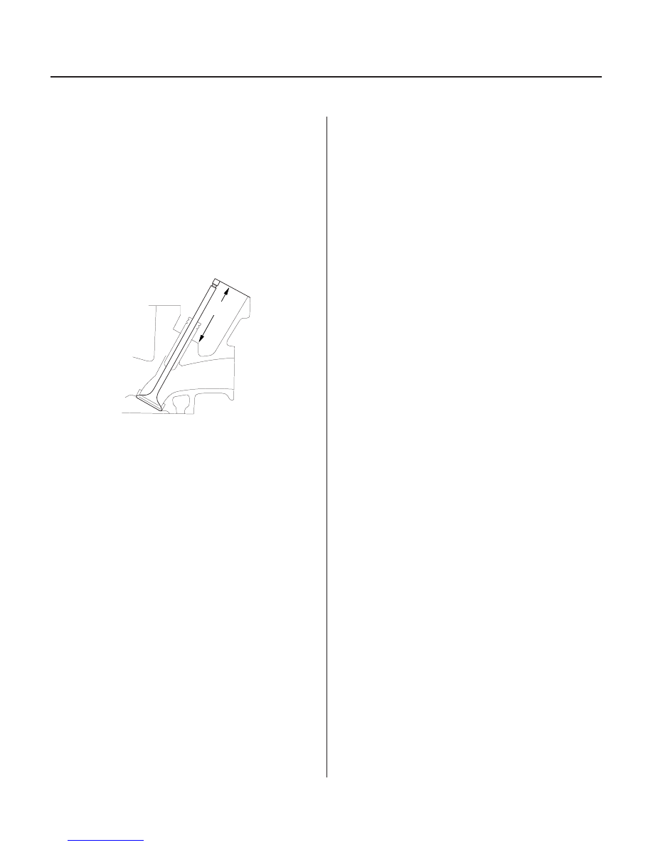
Intake Valve Stem Installed Height
Standard (New): 46.75

47.55 mm

(1.841

1.872 in.)

Service Limit:

47.80 mm (1.882 in.)

Exhaust Valve Stem Installed Height
Standard (New): 46.68

47.48 mm

(1.838

1.869 in.)

Service Limit:

47.73 mm (1.879 in.)

6-52

Cylinder Head

Valve Seat Reconditioning (cont’d)

A

8. Insert the intake and exhaust valves in the head and

measure the valve stem installed height (A).

9. If the valve stem installed height is over the service

limit, replace the valve and recheck. If it is still over
the service limit, replace the cylinder head; the
valve seat in the head is too deep.

03/07/29 09:11:53 61S0X050_060_0052

*01

*02

*03

S0X4A00A14680200000KCAT00

Special Tools Required

6-53

Valve, Spring, and Valve Seal Installation

F

D

E

C

A

B
07PAD-0010000
NOTE: Use 5.5 mm side.

F

D

E

C

F

D

E

C

07757-PJ1010A

A

• Stem seal driver 07PAD-0010000
• Valve spring compressor attachment

07757-PJ1010A

• Valve spring compressor,

KD383 with No. 32 jaws, or CF811, commercially
available

• Valve guide seal installer,

KD3372, commercially available

1. Coat the valve stems with new engine oil. Install

the valves in the valve guides.

2. Check that the valves move up and down smoothly.

3. Install the spring seats on the cylinder head.

4. Install the new valve seals (A) using the valve guide

seal installer (B).

NOTE: Exhaust valve seals (C) have a black spring
(D) and intake valve seals (E) have a white spring
(F); they are not interchangeable.

5. Install the valve spring and valve retainer. Place the

end of the valve spring with closely wound coils
toward the cylinder head.

6. Install the valve spring compressor. Compress the

spring and install the valve keepers.

7. Lightly tap the end of each valve stem two or three

times with a plastic mallet (A) to ensure proper
seating of the valve and valve keepers. Tap the
valve stem only along its axis so you do not bend
the stem.

03/07/29 09:11:54 61S0X050_060_0053

*01

01

03

S0X4A00A14616700000KCAT00

Specified torque:

8 x 1.25 mm
24 N·m (2.4 kgf·m, 17 lbf·ft)
Apply new engine oil to the bolt threads and
flange

6-54

Cylinder Head

Camshaft, Rocker Arm, Camshaft Seal, and Pulley Installation

8 x 1.25 mm
22 N·m (2.2 kgf·m, 16 lbf·ft)

D

B

C

A

A

8 x 1.25 mm
22 N·m (2.2 kgf·m, 16 lbf·ft)

B

1. Apply a light coat of new engine oil around the

camshaft oil seal.

2. Gently tap the new camshaft oil seal (A) into the

cylinder head.

– 1 Tap the new camshaft oil seal in squarely.
– 2 Tap the oil seal in the cylinder head about

0.5

1.5 mm (0.02

0.06 in.) from the surface

of the cylinder head.

3. Insert the camshaft (B) into the cylinder head, then

install the camshaft thrust cover (C). Always use a
new O-ring (D).

4. Check that the oil seal lips are not distorted.

5. Loosen the valve adjusting screws.

6. Set the rocker arm assembly in place and loosely

install the bolts. Make sure that the rocker arms are
properly positioned on the valve stems.

7. Tighten each bolt two turns at a time in the

sequence shown to ensure that the rockers do not
bind on the valves.

8. Install the injector base (A). Always use a new

gasket (B).

03/07/29 09:11:55 61S0X050_060_0054

*02

*01

S0X4A00A14600000000KCAT00

6-55

6-55

Cylinder Head Installation

8 x 1.25 mm
22 N·m (2.2 kgf·m, 16 lbf·ft)

12 x 1.25 mm
90 N·m (9.2 kgf·m, 67 lbf·ft)

B

A

D

D

A

B

B

A

C

9. Install the back cover (A), then install the camshaft

pulley (B).

Install the cylinder heads in the reverse order of
removal:

1. Clean the cylinder head and block surfaces.

2. Clean and install the oil control orifices (A) with

new O-rings (B).

3. Install the dowel pins (C) and new cylinder head

gaskets (D).

(cont’d)

Apply new engine oil to the bolt threads.

03/07/29 09:11:56 61S0X050_060_0055


Content   ..  51  52  53  54   ..