Great Wall Florid. Manual - part 65


  Index      Great Wall     Great Wall Florid - service repair manual 2008 year


Search            copyright infringement  


Content   ..  63  64  65  66   ..


Great Wall Florid. Manual - part 65


GWFLORID Maintenance Manual

258

7.  Disconnect the wire harness of the left & right fog lamps.

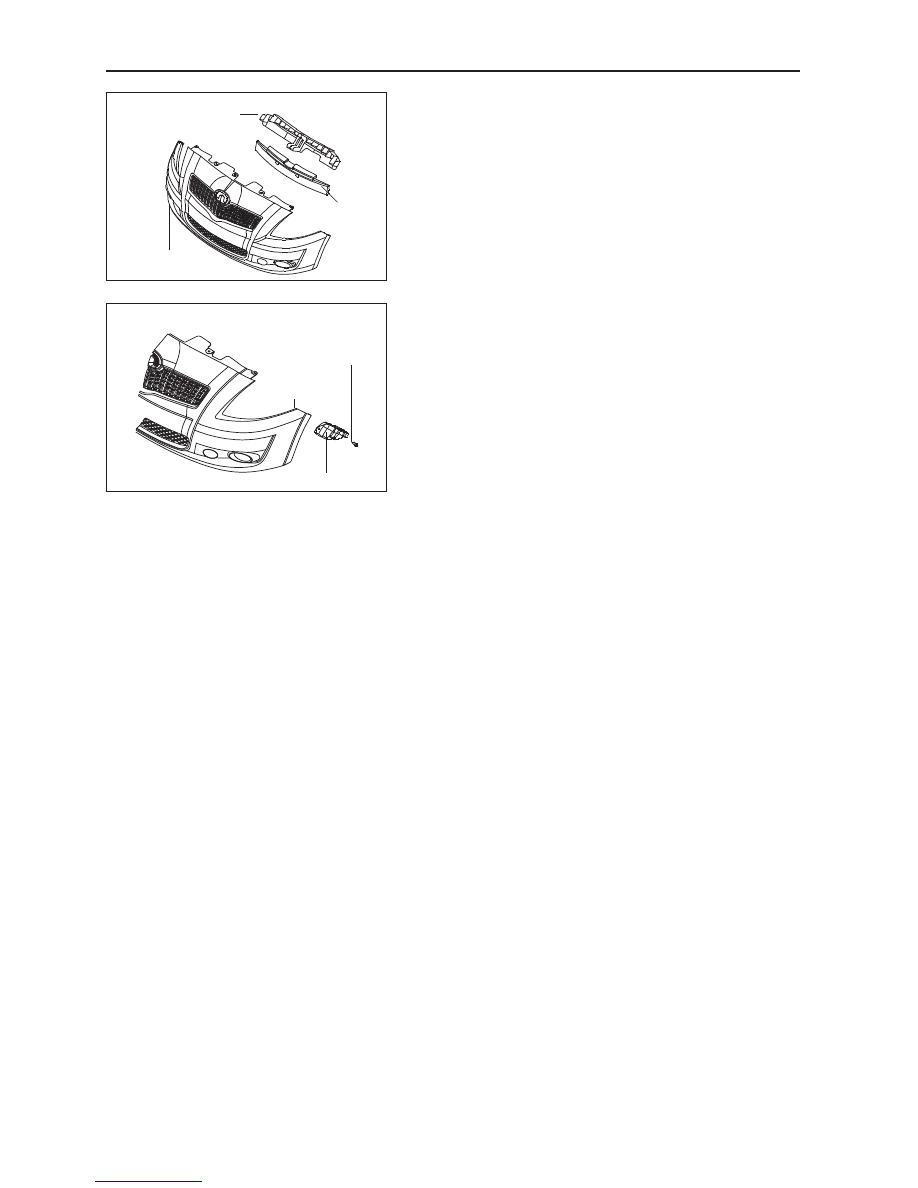
8.  Remove the bumper attachments.

Remove the front bumper plastic support and energy absorb-

ing block from the vehicle body respectively.

9.  Remove the bumper bracket.

Screw off the cross slot & concave hexagon head self-tapping 

screw and large washer subassembly (Q2756319+Q422) on the 

left / right side mounting bracket of the front bumper, and pull 

the left / right side mounting bracket out.

Front bumper body

Front bumper body

Front bumper energy 

absorbing block

Front bumper plastic 

support

Front bumper left side mounting bracket

Cross slot & concave 

hexagon head self-

tapping screw and large 

washer subassembly

259

Vehicle Body

Rear Bumper

Components

Rear bumper removal

1.  Remove the trim panel.

Screw off the cross slot & concave hexagon head self-tap-

ping screw and large washer subassembly, which are on the 

rear bumper's left & right trim panel, the rear bumper trim 

panel buckle, and the expansion button whose bottom is con-

nected with the bumper body. Then pull the left & right trim 

panel of the rear bumper off.

1

13

9

5

3

12

7

4

14

16

15

11

18

6

1

1

1

13

13

13

11

17

3

2

10

8

Rear bumper body

Rear bumper left side trim panel

Cross slot & con-

cave hexagon head 

self-tapping screw 

and large washer 

subassembly

Rear bumper trim 

panel buckle

Expansion button

1.  Cross slot & concave hexagon head self-tapping screw and large 

washer subassembly

2.  Rear mounting bracket LH of the rear bumper

3.  Rear bumper mounting bolt

4.  Hexagon nut for flange face

5.  Rubber cushion of the rear bumper central mounting bracket

6.  Rear bumper central mounting bracket bolt

7.  Central left mounting bracket of the rear bumper

8.  Central right mounting bracket of the rear bumper

9.  Rear mounting bracket RH of the rear bumper

10. Front mounting bracket RH of the rear bumper

11. Rear bumper trim panel buckle

12. Rear bumper right trim panel

13. Expansion button

14. Rear bumper body 

15. Rear bumper plastic buffer anchor

16. Rear bumper drawbar close lid

17. Rear bumper left trim panel 

18. Front mounting bracket LH of the rear bumper 

GWFLORID Maintenance Manual

260

2.  Remove the nut and gasket.

Screw off the hexagon nut for flange face from the rear bum-

per left & right side central mounting bolt, and the rubber 

cushion of the rear bumper left & right side central mounting 

bracket.

3.  Remove the expansion button connecting the left & 

right side bracket below the rear bumper and vehicle 

body.

4.  Remove the bumper mounting bolt.

Screw off the rear bumper mounting bolt connecting the left 

& right side above the rear bumper and vehicle body.

5.  Pull the bumper out.

Pull the rear bumper out of the left & right side bracket of 

the rear bumper, and make the central part of the rear bum-

per slide out along the rear bumper central mounting bracket 

bolt.

6.  Remove the three rear bumper plastic buffer anchor 

from the rear impact beam.

Rear bumper body

Rear bumper body 

Rear bumper body

Rear bumper body 

Rear bumper

Rear bumper plastic buffer anchor

Central left mounting 

bracket of the rear bumper

Rear mounting bracket 

LH of the rear bumper

Front mounting bracket 

LH of the rear bumper  

Rear bumper central 

mounting bracket bolt

Rear bumper mounting bolt

Expansion button

Hexagon nut for flange face

Rubber cushion of the   

rear bumper central 

mounting bracket 

261

Vehicle Body

7.  Remove the front bracket.

Screw off the cross slot & concave hexagon head self-tap-

ping screw and large washer subassembly on the left & right 

front mounting bracket of the rear bumper, and pull the left 

& right front mounting bracket of rear bumper out.

8.  Remove the rear bracket.

Screw off the cross slot & concave hexagon head self-tap-

ping screw and large washer subassembly on the left & right 

rear mounting bracket of the rear bumper, and pull off the 

left & right rear mounting bracket of the rear bumper.

Engine hood lock cable removal and installa-
tion

Removal

1.  Open the engine hood.

2.  Remove the engine hood release lever from the dash-

board.

3.  Remove the cable from the engine hood release lever

4.  Remove the bolts and engine hood lock latch release 

mechanism.

5.  Remove the cable from the engine hood lock latch re-

lease mechanism assembly.

Installation

Areas of Importance: Different metals making direct 

contact will accelerate corrosion. Make sure to use the 

correct fastening piece to avoid premature corrosion.

1.  Install the cable onto the engine hood lock latch re-

lease mechanism assembly.

2.  Install the engine hood lock latch release mechanism 

assembly with the bolts.

3.  Install the cable onto the engine hood lock latch re-

lease lever.

4.  Install the engine hood release lever onto the dash-

board.

Rear bumper body

Rear bumper body 

Rear mounting bracket LH of the rear bumper  

Cross slot & concave hexagon head self-

tapping screw and large washer subassembly

 Front mount-

ing bracket LH of 

the rear bumper

Cross slot & concave 

hexagon head self-tap-

ping screw and large 

washer subassembly

Engine hood 

lock latch release 

mechanism

Cable

Bolt

Dashboard

Release lever


Content   ..  63  64  65  66   ..