Fiat Doblo Panorama (2019 year). Manual - part 7


  Index      Fiat     Fiat Doblo Panorama (2019 year) - manual in english


Search            


Content      ..     5      6      7      8     ..


Fiat Doblo Panorama (2019 year). Manual - part 7


 STARTING AND DRIVING

106

WARNING

95)

Press the clutch pedal fully to shift

gears correctly. It is therefore essential that

there is nothing under the pedals: make

sure the mats are lying flat and do not get

in the way of the pedals.

IMPORTANT

25)

Do not drive with your hand resting

on the gear lever as the force exerted,

even if slight, could lead over time to

premature wear of the gearbox internal

components. The clutch pedal should be

used only for gear changes. Do not drive

with your foot resting on the clutch pedal,

however lightly. For versions/markets

where provided, the electronic clutch

control could cut in by interpreting the

incorrect driving style as a fault.

COMFORT-MATIC/

DUALOGIC

TRANSMISSION

The vehicle is equipped with an

electronically controlled mechanical

transmission (Comfort-Matic or

Dualogic) which has two operating

modes: MANUAL and AUTO.

The transmission consists of a

traditional manual transmission with a

lever fig. 134, to which an electronically

controlled electro-hydraulic device has

been added to automatically control

the clutch and gear the engagement.

26)

134

F0V0324

MANUAL MODE

WARNING For the correct use of the

system only use your right foot to

operate the pedal unit.

Press the brake pedal.

Start the engine.

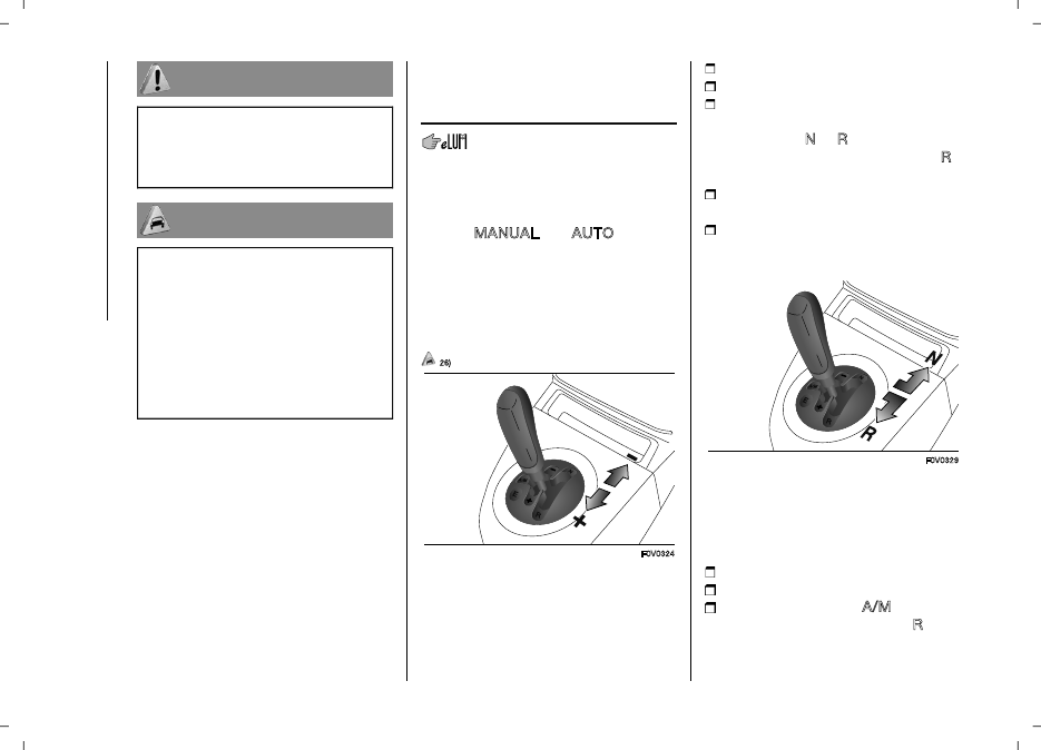
Push the transmission lever towards

+ fig. 134 to engage the first gear (if it

is coming from N or R, simply place

the lever in the middle position) or in R

fig. 135 to engage reverse gear.

Release the brake pedal and press

the accelerator pedal.

In driving conditions, push gear lever

towards + to shift up or towards – to

shift down.

135

F0V0329

AUTOMATIC MODE

WARNING To use the system correctly,

it is advisable to only use your right foot

to operate the pedals.

Press the brake pedal.

Start the engine.

Push the shift lever to A/M fig. 136

to enable automatic mode or to R

fig. 135 to engage reverse; push the

shift lever towards + (shift up) fig. 134

-------------------------------------------------------------------------------------------------------------------------------------------------------------

107

to engage first gear (if starting from

N or R, simply move the lever to the

middle position).

Release the brake pedal and press

the accelerator pedal.

136

F0V0326

It is possible to use the ECO

(Economy) function with this mode,

which reduces consumption. Press

button E fig. 137 to turn this function

on.

137

F0V0323

MESSAGES ON THE

DISPLAY

A dedicate message appears on the

display in the following cases:

Reduce gear changes

The warning light

comes on in

the panel (together with the message

shown in the display) to signal the

incorrect use of the transmission by the

driver.
Manual mode unavailable
Automatic method unavailable
Clutch overheating
Brake pedal pressure
Press brake pedal

Delayed start-

up
Gear not available
Manoeuvre not allowed
Press brake pedal and repeat

manoeuvre
Positioning of the gear lever at N

(neutral)

27) 28) 29)

IMPORTANT

26)

Avoid keeping your hand placed on

this lever in between gear changes or

Auto/Manual mode.

27)

If the warning light (together with the

message in the display) continues to

remain on in the panel, contact a Fiat

Dealership.

28)

If the message is still shown in the

display, contact a Fiat Dealership.

29)

To keep the clutch in good condition,

do not use the accelerator to keep the

car stationary (e.g. when stopped facing

uphill); the clutch could be damaged by

overheating. Use the brake pedal instead

and operate the accelerator only when you

are ready to set off.

START&STOP

SYSTEM

IN BRIEF

The Start&Stop device automatically

stops the engine each time the

vehicle is stationary and starts it again

when the driver wants to move off.

This improves the efficiency of the

vehicle by reducing fuel consumption,

the emission of harmful gases and

noise pollution.

OPERATING MODE
Stopping the engine

WITH MANUAL GEARBOX

With the vehicle stationary, the engine

stops with the gearbox in neutral and

the clutch pedal released.

-------------------------------------------------------------------------------------------------------------------------------------------------------------

 STARTING AND DRIVING

108

WITH ROBOTISED GEARBOX

The engine cuts out if the vehicle stops

with the brake pedal pressed.

This condition can be maintained even

if the brake pedal is not depressed, if

the gear lever is in position N.

Note: The engine can only be stopped

automatically after a speed of about 10

km/h is reached, to prevent the engine

from being repeatedly stopped when

driving at walking pace.

The engine being stopped is signalled

by a fig. 138 symbol on the display,

depending on the trim level.

138

F0V0040

With the device activated, for reasons

of comfort, limiting emissions and

safety, the engine does not stop in

certain conditions.

Restarting the engine

WITH MANUAL GEARBOX

Depress the clutch pedal to restart the

engine.

WITH ROBOTISED GEARBOX

If the gear lever is in position N, place it

in any other gear, otherwise release the

brake pedal or move the gear lever to

(+), (–) or R.

For reasons of comfort, limiting

pollutant emissions and safety

purposes, the power unit can restart

automatically without any action on

behalf of the driver.

MANUAL ACTIVATION

AND DEACTIVATION

The system can be

activated/deactivated using the button

(A) fig. 139 on the control panel.
When the function is not active,

the button LED is on. In addition, on

some versions, additional information

concerning the deactivation or

activation of the Start&Stop system

is given through a message on the

display.

SAFETY FUNCTIONS

In engine cut-out conditions through

the Start&Stop system, if the driver

unfastens his/her seat belt and opens

the driver's door or the passenger

door, the engine can be restarted only

by using the key.

139

F0V0514

The driver is notified of this condition

by a buzzer, through the instrument

panel warning light fig. 138 flashing

and, where provided, by a message in

the display.

VEHICLE INACTIVITY
Versions with dummy pole fig. 140

If the vehicle is inactive, special care

must be taken to disconnect the

battery electrical power supply.

The procedure must be performed

by disconnecting the quick release

negative terminal (A) from the dummy

negative terminal (B); this is because a

battery status monitoring sensor (D) is

fitted on the negative battery terminal

(C) and should never be disconnected

except for when the battery is actually

replaced.

-------------------------------------------------------------------------------------------------------------------------------------------------------------

109

140

F0V0042

Versions without dummy pole

fig. 141

In case of car inactivity, special

attention must be paid due to the

disconnection of the battery power

supply.

The procedure must be performed

by disconnecting the connector (A)

(pressing the button (B)) from the

sensor (C) monitoring the battery

conditions, on the negative pole (D) of

the battery. This sensor should never

be disconnected from the pole except

if the battery is replaced.

96)

141

F0V0218

EMERGENCY STARTING

When jump starting, never connect

the negative cable (–) of the auxiliary

battery to the negative pole (C) of

the car battery, but rather to the

dummy terminal (B) or to another

engine/gearbox earthing point fig. 142.

142

F0V0043

97) 98) 99) 100)

WARNING

96)

If the battery needs to be replaced,

always contact a Fiat Dealership. Replace

the battery with a new one of the same

type and specifications.

97)

Before opening the bonnet, make sure

that the vehicle is switched off and the key

is in the OFF position. Please follow the

instructions on the decal near the front

crossmember. It is advisable to extract

the key when there are other people in the

vehicle.

98)

The vehicle should always be

evacuated after the key has been removed

or turned to the OFF position. When

refuelling, make sure that the vehicle

is switched off with the key in the OFF

position.

99)

For vehicles with robotised gearbox,

if the engine is stopped downhill, the

engine must be restarted by the gear lever

towards (+) or (-) without releasing the

brake pedal. For vehicles with robotised

gearbox and Hill Holder function, in case

of engine automatic stop with the car

downhill, the engine must be restarted

moving the gear lever towards (+) or (-)

without releasing the brake pedal, so that

the Hill Holder function becomes available,

as it works only with engine running.

100)

If climate comfort is to be favoured,

the Start&Stop system can be deactivated,

for a continuous operation of the climate

control system.

-------------------------------------------------------------------------------------------------------------------------------------------------------------

 STARTING AND DRIVING

110

TPMS (Tyre

Pressure

Monitoring System)

(for versions/markets, where provided)

101) 102) 103) 104) 105) 106) 107) 108) 109)

DESCRIPTION

The system warns the driver if one or

more tyres are flat by turning on the

warning light on the instrument

panel (together with a warning

message and an acoustic signal).

The indication continues until the

pressure corresponds to or exceeds

that specified for cold tyres. After the

automatic update of the system, the

tyre pressure control warning light

switches off. You may need to drive the

vehicle for about 20 minutes at a speed

higher than 20 km/h to allow the TPMS

to receive this information.
Tyre pressure must always be adjusted

according to the cold inflation pressure.

Cold tyre inflation pressure is the tyre

pressure after letting the vehicle stand

for at least three hours or a travel

shorter than 1.6 km after an interval of

three hours.
The cold tyre inflation pressure must

not exceed the maximum inflation

pressure value printed on the side of

the tyre.
NOTE

The TPMS does not replace the

normal tyre maintenance service and

does not indicate any fault in a tyre.

Therefore, the TPMS should not be

used as pressure switch while adjusting

the tyre inflation pressure.

Driving with insufficient tyre pressure

causes their overheating and can result

in tyre failure. The low inflation pressure

reduces fuel efficiency and tyre tread

life and may also affect handling and

braking performance of the vehicle.

The TPMS does not replace the

correct tyre maintenance. It is up to

the driver to maintain the correct

tyre pressure level measuring it with

a suitable pressure switch. This is

necessary even if the decrease in the

inflation pressure value does not cause

the tyre pressure control warning light

to switch on.

The TPMS warns the driver of any

condition of insufficient tyre pressure.

If this drops below the insufficient

pressure limit for any reason including

low temperature and normal pressure

loss of the tyre.

The seasonal temperature changes

affect tyre pressure.

WARNING Monitoring and maintaining

the correct pressure in all four tyres are

particularly important.
Tyre pressure monitoring system

low pressure warning
WARNING In the case of deflation

of more than one tyre sequentially,

without switching off and on the

engine, from the second tyre involved

the acoustic signal is not activated,

only the dedicated signal is shown

on the display. To prevent the signal

from being stored in the event of

pressure loss of a subsequent tyre

(with deactivation of the acoustic

signal), the ignition key must be turned

to MAR and then to STOP, each time

pressure is restored.

TPMS operation faults

The system fault is indicated by the

warning light

which first flashes for

75 seconds and then stays on steadily.

WARNING

101)

The TPMS is optimised for the

original tyres and wheels provided. TPMS

pressures and alerts have been defined

according to the size of the tyres mounted

on the vehicle. Using equipment with

different size, type or kind may cause

irregular system operation or sensor

damage. Non-original spare wheels can

damage the sensor. Do not use tyre

sealant or balancing weights if the vehicle

-------------------------------------------------------------------------------------------------------------------------------------------------------------

111

is equipped with TPMS as these may

damage the sensors.

102)

If the system signals a pressure drop

on a specific tyre, it is recommended to

check the pressure on all four tyres.

103)

The TPMS does not relieve the

driver from the obligation to check the

tyre pressure every month; it is not even

to be considered a replacing system for

maintenance or a safety system.

104)

Tyre pressure must be checked with

tyres cold. Should it become necessary for

whatever reason to check pressure with

warm tyres, do not reduce pressure even

though it is higher than the prescribed

value, but repeat the check when tyres are

cold.

105)

The TPMS cannot indicate sudden

tyre pressure drops (for example when a

tyre bursts). In this case, stop the vehicle,

braking with caution and avoiding abrupt

steering.

106)

The system only warns that the tyre

pressure is low: it is not able to inflate

them.

107)

Insufficient tyre inflation increases fuel

consumption, reduces the tread duration

and may affect the capacity to drive safely.

108)

Always refit the valve stem cap after

inspecting or adjusting tyre pressure. This

prevents dampness or dirt from entering

the valve stem and thus the pressure

control sensor from being damaged.

109)

The tyre repair kit (Fix&Go) provided

with the vehicle (for versions/markets,

where provided) is compatible with the

TPMS sensors; using sealants not

equivalent with that in the original kit may

adversely affect its operation. If sealants

not equivalent with the original one are

used, it is recommended to have the

TPMS sensor operation checked by a

qualified repair centre.

SPEED BLOCK

(for versions/markets, where provided)

The vehicle is equipped with a speed

limitation function that can be set on

the user's request to one of four default

values: 90, 100, 110, 130 km/h.

To activate/deactivate this function,

contact a Fiat Dealership.

Following the operation, a sticker will

be applied to the windscreen showing

the top speed setting.

IMPORTANT The speedometer could

indicate a higher maximum speed than

the effective one, set by the Dealership,

in accordance with the regulations in

force.

CRUISE CONTROL

(constant speed

regulator)

(for versions/markets, where provided)

IN BRIEF

This is an electronic driving aid that

allows you to drive at a speed of

above 30 km/h on long and straight

dry roads (e.g. motorways) with few

driving changes (e.g. motorway

routes) at a preset speed without

having to press the accelerator pedal.

It is therefore not recommended to

use this device on extra-urban roads

with traffic. Do not use the device in

town.

Activating the device

When the device is activated, warning

light

comes on together with the

relevant message in the instrument

panel (for versions/markets where

provided).
The speed adjustment function cannot
be activated in 1st or reverse gear; it is
advisable to activate the function in 4th

or higher gears.
When travelling downhill with the device

activated, the vehicle speed may

exceed the memorised one.

-------------------------------------------------------------------------------------------------------------------------------------------------------------

 STARTING AND DRIVING

112

110) 111)

Storing vehicle speed

Proceed as follows:

turn ring nut (A) fig. 143 to the ON

position and press the accelerator

pedal so that the vehicle reaches the

desired speed;

move the stalk upwards (+) for at

least one second, then release it: the

vehicle speed is memorised and you

can therefore release the accelerator

pedal.
If necessary (when overtaking for

instance) acceleration is possible

by simply pressing the accelerator

pedal: releasing the accelerator pedal,

the vehicle will return to the speed

memorised previously.

Restoring the stored

speed

If the device has been deactivated, for

example by depressing the brake or

clutch pedal, the stored speed can be

restored as follows:

accelerate progressively until a speed

close to that stored is reached;

143

F0V0092

engage the gear selected at the time

that the speed was stored;

press the (B) fig. 143 button.

Increasing the stored

speed

This can be done in two ways:

by pressing the accelerator and

memorizing the new speed reached;
or

by moving the stalk upwards (+).

Each operation of the lever will

correspond to a slight increase in

speed of about 1 km/h, while keeping

the lever upwards will increase the

speed continuously.

Reducing the

memorised speed

This can be done in two ways:

by deactivating the device and then

storing the new speed

or

by moving the stalk downwards

(-) until the new speed, which will

automatically remain memorised, is

reached.
Each movement of the stalk will

correspond to a slight reduction in

speed of about 1 km/h, while keeping

the stalk held downwards will decrease

the speed continuously.

Deactivating the device

The device can be switched off by the

driver in the following ways:

by turning ring nut A to the OFF

position;

if the engine is stopped (leaving

the stalk ring nut at ON), when the

ignition key is next turned to ON, Cruise

Control will be activated automatically.

Deactivating the

function

The device can be switched off by the

driver in the following ways:

by pressing the brake pedal when

the device is adjusting the speed:

by pressing the clutch pedal when

the device is adjusting the speed;

by pressing button (B) fig. 143 when

the device is adjusting the speed (for

versions/markets, where provided);

-------------------------------------------------------------------------------------------------------------------------------------------------------------

113

by pressing the accelerator pedal

(in this case the system is not actually

turned off but the acceleration request

takes priority; the cruise control

remains activated, without the need to

the press button (B) fig. 143 to restore

the previous conditions once the

acceleration is over).
The device is automatically switched off

in the following cases:

if the ABS or ESC systems intervene;

with the vehicle speed below the set

limit;

in the event of system failure.

WARNING

110)

While driving with the device active,

never move the gear lever to neutral.

111)

In the event of device faults or

failures, turn knob (A) to OFF and contact

a Fiat Dealership.

TRACTION PLUS

SYSTEM

(for versions/markets, where provided)

Traction Plus is a driving aid, useful

for setting off in poor grip conditions

(snow, ice, mud, etc.) which allows the

drive force to be distributed in the best

way over the front axle when one wheel

is slipping.

Traction Plus acts by braking the

wheels with poor grip (or those

slipping more than the others), thereby

transferring the drive force to those

which have greater grip on the ground.

This function can be turned on

manually by pressing the button (A)

fig. 144 on the dashboard and works

below a level of 50 km/h.

Over this speed, it is automatically

deactivated and it is reactivated again

when the speed is below 50 km/h.

144

F0V0575

Traction Plus operation

The system is deactivated when

starting. To activate the Traction Plus

system, press the button (A) fig. 144.

The activation of the Traction Plus

system involves the following functions

being switched on:

inhibition of the ASR function, in

order to fully exploit the engine torque;

the differential locking effect on

the front axle, through the braking

system, to improve traction on irregular

grounds.

If the "Traction Plus" system is faulty,

the "general failure" instrument panel
warning light

comes on steady.

PARKING SENSORS

These are located in the rear bumper

fig. 145 and their function is to inform

the driver, through an intermittent

beeping noise, about the presence of

obstacles behind the vehicle.

145

F0V0077

-------------------------------------------------------------------------------------------------------------------------------------------------------------

 STARTING AND DRIVING

114

ACTIVATION/

DEACTIVATION

The sensors are automatically activated

when reverse gear is engaged. As the

obstacle behind the vehicle gets closer

to the bumper, the frequency of the

acoustic signal increases.

Detection distances

If several obstacles are detected by

the sensors, only the nearest one is

considered.

112)

OPERATION WITH A

TRAILER

Parking sensor operation is

automatically deactivated when the

electric cable plug of the trailer is

inserted into the vehicle tow hook

socket. The sensors are automatically

reactivated when the trailer's cable plug

is removed.

WARNING

If you wish to leave the tow hook fitted

without towing a trailer, it is advisable

to contact a Fiat Dealership for the

relevant system update operations

because the tow hook could be

detected as an obstacle by the central

sensors.

IMPORTANT NOTES

113)

When parking, take the utmost care

over obstacles that may be above or

under the sensor.

Sometimes, objects located very

near the rear of the vehicle are not

detected and could therefore damage

the vehicle or be damaged themselves.
The following conditions may influence

the performance of the parking

assistance system:

Reduced sensor sensitivity and a

reduction in the parking assistance

system performance could be due

to the presence on the surface of the

sensor of: ice, snow, mud, thick paint.

The sensor may detect a non-

existent obstacle (echo noise) due to

mechanical noises, for example when

washing the vehicle, in case of rain,

strong wind, hail.

The signals sent out by the sensors

can be altered by dirt, snow or

ice deposited on the sensors or

by ultrasound systems (e.g. truck

pneumatic brakes or pneumatic drills)

near the vehicle.

The performance of the parking

assistance system may also be

affected by the position of the sensors.

For example by a change in the

ride setting (caused by the wear of

the shock absorbers, suspension),

changing the tyres, overloading the

vehicle and carrying out specific tuning

operations that require the vehicle to be

lowered.

Detection of obstacles in the upper

part of the vehicle (particularly in the

case of vans or chassis cabs) may not

be guaranteed because the system

detects obstacles that could strike the

lower part of the vehicle.

The parking sensors work properly

with the swing doors closed.

If they are open, they can cause the

system to send false signals: always

close the rear doors.

Do not apply stickers to the sensors.

WARNING

112)

The sensor must be free of mud,

dirt, snow or ice in order for the system

to work. Be careful not to scratch or

damage the sensors while cleaning them.

Avoid using dry, rough or hard cloths.

The sensors must be washed using

clean water, with the addition of vehicle

shampoo if necessary. When using special

washing equipment such as high pressure

jets or steam cleaning, clean the sensors

very quickly keeping the jet more than 10

cm away.

113)

Parking manoeuvres, however, are

always the driver’s responsibility. While

carrying out these manoeuvres, always

make sure that no people (especially

children) or animals are in the area

-------------------------------------------------------------------------------------------------------------------------------------------------------------

115

concerned. The parking sensors are used

to assist the driver, who must never allow

his attention to lapse during potentially

dangerous manoeuvres, even those

executed at low speeds.

REAR CAMERA

(PARKVIEW® REAR

BACK UP CAMERA)

114)

30) 31) 32)

DESCRIPTION

The rear video camera is located above

the license plate holder compartment

fig. 146 or beneath the opening handle

fig. 147 respectively in case of tilting or

swinging doors.

146

F0V0129

147

F0V0130

Camera activation/deactivation

Every time reverse is engaged, the

display fig. 148 shows the area around

the vehicle, as seen by the rear

camera.

The images are shown on the display

together with a warning message.

When reverse is not engaged, the rear

camera may be switched on using

the setting menu (Camera ON/OFF).

If the "Camera Delay" option is not

activated, the image of the camera

will be deactivated as soon as reverse

is disengaged and the display will go

back to Navigation or Audio mode.

By activating the "Camera Delay"

option on the menu, the camera

image will continue to be viewed for

up to 10 seconds after disengaging

reverse except for when the following

conditions occur:

vehicle speed above 13 km/h;

gear lever in P (Park - versions

with automatic transmission, where

provided);

ignition device in the STOP position.

148

F0V0261

When the gear lever is no longer in

reverse and the "Camera Delay" setting

is on, a button for deactivating the

display of the image from the camera

appears on the Uconnect™ system

display along with the images to the

rear.

NOTE If the tailgate is not closed

correctly, the rear camera cannot

-------------------------------------------------------------------------------------------------------------------------------------------------------------

 STARTING AND DRIVING

116

provide an accurate image of the area

behind the vehicle. The image will

appear on the display together with a

warning message.

NOTE The displayed image may look a

bit distorted.

DISPLAY AND MESSAGES

When the rear camera is active, a

grid appears with multi-colour static

lines superimposed on the picture to

highlight the vehicle’s width.

The various coloured areas indicate

the distance from the rear part of the

vehicle. The table below shows the

approximate distances for each area:

Zone (see figure)

Distance from

rear of vehicle

Red (A)

(0 ÷30 cm)

Yellow (B)

30 cm - 1 m)

Green (C)

(1 m or more)

WARNING In some circumstances,

such as with ice, snow or mud on the

surface of the camera, the camera

sensitivity may be reduced.

WARNING When parking, take the

utmost care over obstacles that may

be above or under the camera range.

WARNING

114)

Parking and other potentially

dangerous manoeuvres are, however,

always the driver’s responsibility. While

carrying out these manoeuvres, always

make sure that no people (especially

children) or animals are in the area

concerned. The camera is an aid for the

driver, but the driver must never allow

his/her attention to lapse during potentially

dangerous manoeuvres, even those

executed at low speeds. Always keep a

slow speed, so as to promptly brake in the

case of obstacles.

IMPORTANT

30)

It is vital, for correct operation, that the

camera is always kept clean and free from

any mud, dirt, snow or ice. Be careful not

to scratch or damage the camera while

cleaning it. Avoid using dry, rough or hard

cloths. The camera must be washed using

clean water, with the addition of vehicle

shampoo if necessary. In washing stations

which use steam or high-pressure jets,

clean the camera quickly, keeping the

nozzle more than 10 cm away from the

sensors. Also, do not apply stickers to the

camera.

31)

To prevent damage to the vehicle, the

rear camera should be used only as an

additional parking aid; it is not capable

of viewing all the obstacles and objects

along the vehicle’s path during parking

manoeuvres.

32)

To prevent damage to the vehicle,

the driver should proceed as slowly as

possible when parking to be able to stop

promptly if necessary. We recommend the

driver check the area behind the vehicle

often while parking.

REFUELLING THE

VEHICLE

PETROL ENGINES

Only use unleaded petrol, with an

octane number (R.O.N.) not lower than

95.
WARNING Never introduce leaded

petrol to the tank, even in small

amounts in an emergency, as this

would damage the catalytic converter

beyond repair.

DIESEL ENGINES
Operation at low temperatures

Only use Diesel for motor vehicles

(EN590 specification).

In order to avoid these problems,

different types of Diesel are distributed

according to the season: summer

type, winter type and Arctic type

(cold, mountain areas). If refuelling

with diesel whose specifications are

not suitable for the usage temperature,

it is advisable to mix PETRONAS

-------------------------------------------------------------------------------------------------------------------------------------------------------------

117

DURANCE DIESEL ART additive in the

proportions shown on the container

with the fuel. Pour the additive into the

tank before the fuel.

When using or parking the vehicle for

a long time in the mountains or cold

areas, it is advisable to refuel using

locally available diesel fuel.

In this case, it is also advisable to keep

the tank over 50% full.

33)

REFUELLING CAPACITY

To ensure that you fill the tank

completely, top up twice after the first

click of the fuel supply gun. Further

top-ups could cause faults in the fuel

feeding system.

FUEL TANK CAP
Opening

1) Open the flap (A) fig. 149 by pulling it

outwards, keep the cap (B) still, insert

the ignition key in the lock and turn it

anticlockwise.

2) Turn the cap anticlockwise and

remove it. The cap has a device (C)

that attaches it to the flap so it cannot

be lost. When refilling, attach the plug

to the flap, as shown.

149

F0V0086

Closing

1) Fit the cap (complete with key) and

turn it clockwise until it clicks once or

more.

2) Turn the key clockwise and extract it,

then close the flap. The sealing may

cause a slight pressure increase in

the tank. A little breathing off, while

slackening the cap is absolutely

normal.

34)

TOPPING UP ADBLUE®

DIESEL EMISSIONS

ADDITIVE (UREA)
Preliminary conditions

AdBlue® freezes at temperatures

lower than -11°C. If the vehicle stands

for a long time at this temperature

refilling could be difficult. For this

reason, it is advised to park the vehicle

in a garage and/or heated environment

and wait for the UREA to return to

liquid state before topping up.

Proceed as follows:

park the vehicle on ground level;

stop the engine by turning the

ignition device to MAR;

open the fuel flap A (A)fig. 150 and

then unscrew and remove the cap

(B) (blue colour) fig. 150 from the

AdBlue® filler.

Refilling with nozzles

You can fill up at any AdBlue®

distributor.

150

F0V0736

Proceed as follows:

insert the AdBlue® nozzle in the

filler, start refilling and stop refilling at

the first shut-off (the shut-off indicates

that the AdBlue® tank is full).

Do not proceed with the refilling, to

prevent spillage

extract the nozzle.

Refilling with containers

Proceed as follows:

-------------------------------------------------------------------------------------------------------------------------------------------------------------

 STARTING AND DRIVING

118

check the expiration date;

read the advice for use on the label

before pouring the content of the bottle

into the AdBlue® tank;

if systems which cannot be screwed

in (e.g. tanks) are used for refilling,

after the indication appears on the

instrument panel display (see "Warning

lights and messages" paragraph in

the "Knowing the instrument panel"

chapter), fill the AdBlue® tank with no

more than 9 litres;

if containers which can be screwed

to the filler are used, the reservoir is

full when the AdBlue® level in the

container stops pouring out. Do not

proceed further.

Operations after refilling

Proceed as follows:

fit the cap (B) fig. 150 back on the

AdBlue® filler by turning it clockwise

and screwing it completely;

set the starter switch to MAR (it is

not necessary to start the engine);

wait for the indication on the

instrument panel to switch off before

moving the vehicle. The indication

may stay on for a few seconds to

approximately half a minute.

If the engine is started and the vehicle

is moved, the indication will remain on

for longer. This will not compromise

engine operation;

if the AdBlue® was topped up when

the tank was empty, see the "Refuelling

" paragraph in the "Technical

Specifications" chapter and wait for 2

minutes before starting the engine.

WARNING If AdBlue® is spilled out of

the filler neck, clean up well the area

and proceed to filling up again. If the

liquid crystallises, eliminate it with a

sponge and warm water.

IMPORTANT

DO NOT EXCEED THE MAXIMUM

LEVEL: this could cause damage

to the reservoir. UREA freezes at

under -11

°

C. Although the system

is designed to operate below the

freezing point of the UREA, it is

advisable not to fill the tank beyond

the maximum level because if the

UREA freezes the system can be

damaged. Follow the instructions

in the "Topping up AdBlue®

(UREA) diesel emissions additive"

paragraph in this chapter.

If the UREA is spilled on painted

surfaces or aluminium, immediately

clean the area with water and use

absorbent material to collect the

fluid that has been spilled on the

ground.

Do not try to start the engine if

UREA was accidentally added to

the Diesel fuel tank, this can result

in serious engine damage, contact

a Fiat Dealership.

Do not add additives or other

fluids to AdBlue®, doing so could

damage the system.

The use of non-conforming

or degraded AdBlue® may lead

to indications appearing on the

instrument panel display (see

"Warning lights and messages"

paragraph in the "Knowing the

instrument panel" chapter).

Never pour AdBlue® into

another container: it could be

contaminated.

In case of damage to the sewage

system of exhaust gas resulting

from the use of additives / tap

water, the introduction of diesel

fuel, or at least by not fulfilling the

requirements, the warranty expires.

If the AdBlue® runs out, see

"Warning lights and messages"

paragraph in the "Knowing

the instrument panel" chapter

to continue using the vehicle

normally.

AdBlue® UREA) storage

AdBlue® (UREA) is considered a very

stable product with a long shelf life.

Stored at temperatures LOWER than

32°C, it has a shelf life of at least one

year.

-------------------------------------------------------------------------------------------------------------------------------------------------------------

119

Follow the instructions on the label of

the container.

35)

NATURAL POWER

VERSIONS

The methane filler is located near the

petrol filler. To access the filler, undo

the cap fig. 151 turning it anticlockwise.

151

F0V0239

The profile of the filler fig. 152 for

refilling is the universal type compatible

with Italian and NGV1 standards.

152

F0V0240

In some European countries adapters

are considered ILLEGAL (e.g. in

Germany).
For service stations with cubic metre

(m3) nozzles (pressure differential) the

check valves must be released by

delivering a small amount of methane

to measure the residual pressure in the

cylinder.
The plates (provided with the vehicle

documentation) contain the date for the

first inspection of the cylinders.

36)

Fuel - Vehicle

compatibility

identification -

Graphic symbol for

informing consumers

in accordance with

EN16942

The symbols shown below aid

recognising the correct fuel type to

be used on your vehicle. Before

proceeding with refuelling, check the

symbols inside the fuel filler flap (where

provided) and compare them with

the symbols shown on the fuel pump

(where provided).

Symbols for petrol powered cars

E5: Unleaded petrol containing up to

2.7% (m/m) oxygen and with maximum

5.0% (V/V) ethanol compliant with

EN228
E10: Unleaded petrol containing up to

3.7% (m/m) oxygen and with maximum

10.0% (V/V) ethanol compliant with

EN228

Symbols for diesel powered cars

B7: Diesel containing up to 7% (V/V)

of FAME (Fatty Acid Methyl Esters)

compliant with EN590
B10: Diesel containing up to 10% (V/V)

of FAME (Fatty Acid Methyl Esters)

compliant with EN16734

Symbols for petrol/methane bi-fuel

cars

E5: Unleaded petrol containing up to

2.7% (m/m) oxygen and with maximum

5.0% (V/V) ethanol compliant with

EN228
E10: Unleaded petrol containing up to

3.7% (m/m) oxygen and with maximum

10.0% (V/V) ethanol compliant with

EN228

-------------------------------------------------------------------------------------------------------------------------------------------------------------

 STARTING AND DRIVING

120

CNG: Automotive methane and bio-

methane compliant with EN16723

IMPORTANT

33)

For diesel engines, use only diesel fuel

for motor vehicles in accordance with

EN590 European specifications. The

use of other products or mixtures may

damage the engine beyond repair and

consequently invalidate the warranty, due

to the damage caused. If you accidentally

introduce other types of fuel into the tank,

do not start the engine. Empty the tank.

If the engine has been run for even an

extremely limited amount of time, you must

not only drain the fuel tank, but the rest of

the supply circuit as well.

34)

Do not approach naked flames or lit

cigarettes to the fuel tank filler: fire risk.

Keep your face away from the fuel filler to

prevent breathing in harmful vapours.

35)

If AdBlue® overheats for a prolonged

period inside the tank to over 50°C (for

example, due to direct solar irradiation),

the AdBlue ® may decompose and

produce ammonia vapours. Ammonia

vapours have a pungent odour when the

cap of the AdBlue ® tank is unscrewed,

therefore be careful not to inhale any

ammonia vapours in the tank outlet. In this

concentration, however, the ammonia

vapours are not harmful or dangerous to

health.

36)

Methane refuelling stations are not

authorised to refill the cylinders when the

inspection date has expired. The check

valve prevents the methane from flowing

back to the fuel filler.

ADDITIVE FOR

DIESEL EMISSIONS

AdBlue (UREA)

The vehicle is equipped with an UREA

fuel injection system and a Selective

Catalytic Reduction catalyst to meet

the emission standards.

These two systems ensure compliance

with the diesel emissions requirements;

at the same time, they ensure fuel-

efficiency, handling, torque and power.

For messages and system warnings,

refer to the "Warning lights and

messages" paragraph in the "Knowing

the instrument panel" chapter.

AdBlue® (UREA) is considered a very

stable product with a long shelf life.

Stored at temperatures LOWER than

32 °C, it has a shelf life of at least one

year.

For more information on the AdBlue®

liquid type, see the “Fluids and

lubricants” paragraph in the “Technical

specifications” chapter.

The vehicle is provided with an

automatic AdBlue® heating system

when the engine starts allowing

the system to work correctly at

temperatures lower than -11 °C.

IMPORTANT AdBlue® freezes at

temperatures lower than -11 °C.

TOWING TRAILERS

IMPORTANT NOTES

The vehicle must be equipped with a

type-approved tow hook and adequate

electrical system to tow trailers.

Installation should be carried out by

specialised personnel who will issue the

required papers for travelling on roads.
Install any specific and/or additional

door mirrors as specified by the

Highway Code.
Remember that when towing a trailer,

steep hills are harder to climb, braking

spaces increase and overtaking takes

longer depending on the overall weight.
Engage a low gear when driving

downhill, rather than constantly using

the brake.
The weight of the trailer on the vehicle

tow hook will reduce the loading

capacity of the vehicle by the same

amount.
To make sure that the maximum

towable weight is not exceeded (given

in the vehicle registration document)

account should be taken of the fully

laden trailer, including accessories and

luggage.
Do not exceed the speed limits specific

to each country you are driving in, in

the case of vehicles towing trailers.

In any case, the top speed must not

exceed 80 km/h.

-------------------------------------------------------------------------------------------------------------------------------------------------------------

121

115) 116)

WARNING

115)

The ABS with which the vehicle

may be equipped will not control the

trailer's braking system. Particular caution

is required on slippery roads.

116)

Never modify the braking system

of the vehicle to control the trailer brake.

The trailer braking system must be fully

independent from the hydraulic system of

the vehicle.

-------------------------------------------------------------------------------------------------------------------------------------------------------------


Content      ..     5      6      7      8     ..