Dodge Neon / Neon SRT-4. Manual - part 400


  Index      Dodge     Dodge Neon / Neon SRT-4 - service repair manual 2005 year


Search            


Content   ..  398  399  400  401   ..


Dodge Neon / Neon SRT-4. Manual - part 400


(3) Remove cowl cover.
(4) Place protective covers over instrument panel

and hood.

(5) Remove the screws and remove the windshield

A-pillar moldings. (Fig. 2)

(6) Using a sharp cold knife, cut urethane adhe-

sive holding the windshield to the A-pillars, roof
header and cowl pinch weld fences (Fig. 3). A power
cutting device can be used if available.

(7) Separate windshield from vehicle.

INTERIOR METHOD

The urethane adhesive holding the windshield to

the opening pinch weld (fence) can be cut using a
sharp cold knife from the exterior of the vehicle.
Using the cold knife method is effective if the wind-
shield is already broken. If the glass must be sal-
vaged, cutting the urethane adhesive from the
interior of the vehicle using a reciprocating or oscil-
lating power knife is recommended.

(1) Remove inside rear view mirror.
(2) Remove instrument panel top cover, refer to

Group 8E, Instrument Panel.

(3) Remove A-pillar trim covers.
(4) Place protective covers over instrument panel

and hood.

(5) Using a reciprocating or oscillating power

knife, cut urethane adhesive holding the windshield
to the A-pillars, roof header and cowl pinch weld
fences. Refer to instructions provided with the equip-
ment being used.

(6) Remove windshield from vehicle.

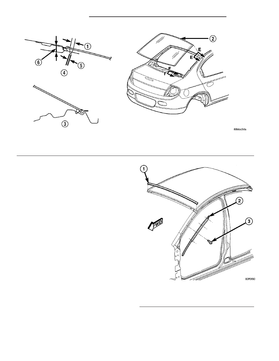
Fig. 1 Rear Window Glass

1 - 9.5 MM
2 - REAR WINDOW
3 - SECTION F-F

4 - SECTION E-E
5 - 3 MM
6 - 12.7 MM

Fig. 2 WINDSHIELD HEADER OUTSIDE MOLDING

1 - WINDSHIELD HEADER MOLDING
2 - A-PILLAR OUTSIDE MOLDING
3 - A-PILLAR

23 - 84

STATIONARY GLASS

PL/SRT-4

WINDSHIELD (Continued)

INSTALLATION

CAUTION: Open the left front door glass before
installing windshield to avoid pressurizing the pas-
senger compartment. If a door is slammed before
urethane bonding is cured, water leaks can result.
Allow the urethane at least 24 hours to cure before
returning the vehicle to use.
To avoid stressing the replacement windshield, the
urethane bonding material on the windshield fence
should be smooth and consistent to the shape of
the replacement windshield. The support spacers
should be cleaned and properly installed on weld
studs or repair screws at bottom of windshield
opening.

(1) Place replacement windshield into windshield

opening and position glass in the center of the open-
ing against the support spacers.

(2) Verify the glass lays evenly against the pinch

weld fence at the sides, top and bottom of the
replacement windshield. If not, the pinch weld fence
must be formed to the shape of the new glass.

(3)

Remove replacement windshield from wind-

shield opening.

(4) Position the windshield inside up on a suitable

work surface with two padded, wood 10 cm by 10 cm
by 50 cm (4 in. by 4 in. by 20 in.) blocks, placed par-
allel 75 cm (2.5 ft.) apart (Fig. 4).

WARNING: DO NOT USE SOLVENT BASED GLASS
CLEANER

TO

CLEAN

WINDSHIELD

BEFORE

APPLYING

GLASS

PREP AND

PRIMER.

POOR

ADHESION CAN RESULT.

(5) Clean inside of windshield with ammonia based

glass cleaner and lint-free cloth.

(6) Apply molding to Top of windshield.
(7) Apply Glass Prep adhesion promoter 25 mm (1

in.) wide around perimeter of windshield and wipe

with clean/dry lint-free cloth until no streaks are vis-
ible.

(8) Apply Glass Primer 25 mm (1 in.) wide around

perimeter of windshield. Allow at least three minutes
drying time.

(9) Using a razor knife, remove as much original

urethane as possible. Do not damage paint on wind-
shield fence.

(10) Apply pinch weld primer 15 mm (.75 in.) wide

around the windshield fence. Allow at least three
minutes drying time.

(11) Apply a 10 mm (0.4 in.) bead of urethane on

center line of windshield fence.

(12) With the aid of a helper, position the wind-

shield over the windshield opening. Align the refer-
ence marks at the bottom of the windshield to the
support spacers.

(13) Slowly lower windshield glass to windshield

opening fence. Guide the molding into proper position
as necessary. Push windshield inward molding is
flush to roof line and A-pillars (Fig. 5).

(14) Clean access urethane from exterior with

Mopar

t, Super Clean or equivalent.

(15) Apply 150 mm (6 in.) lengths of 50 mm (2 in.)

masking tape spaced 250 mm (10 in.) apart to hold
molding in place until urethane cures.

(16) Install A-pillar moldings.
(17) Install cowl cover and wipers.
(18) Install inside rear view mirror.
(19) After urethane has cured, remove tape strips

and water test windshield to verify repair.

Fig. 3 Cut Urethane Around Windshield

1 - COLD KNIFE
2 - WINDSHIELD

Fig. 4 Work Surface Set up and Molding Installation

1 - WINDSHIELD AND MOLDINGS
2 - URETHANE BEAD AROUND GLASS 7mm (.3 in.) FROM EDGE
3 - BLOCKS

PL/SRT-4

STATIONARY GLASS

23 - 85

WINDSHIELD (Continued)

Fig. 5 Lower Windshield Into Position

1 - WINDSHIELD
2 - WINDSHIELD TO FENCE RETAINER
3 - SECTION D-D
4 - SECTION B-B
5 - SECTION C-C
6 - SECTION A-A
(FENCE)

7 - SECTION A-A
(GLASS)
8 - HIGH VISCOSITY ADHESIVE
9 - WINDSHIELD FENCE SUPPORT SPACERS

23 - 86

STATIONARY GLASS

PL/SRT-4

WINDSHIELD (Continued)

WEATHERSTRIP/SEALS

TABLE OF CONTENTS

page

page

B-PILLAR WEATHERSTRIP CHANNEL

REMOVAL

. . . . . . . . . . . . . . . . . . . . . . . . . . . . . 87

INSTALLATION

. . . . . . . . . . . . . . . . . . . . . . . . . 87

FDR GLASS RUN WEATHERSTRIP

REMOVAL

. . . . . . . . . . . . . . . . . . . . . . . . . . . . . 87

INSTALLATION

. . . . . . . . . . . . . . . . . . . . . . . . . 87

OUTER BELT WEATHERSTRIP

REMOVAL

. . . . . . . . . . . . . . . . . . . . . . . . . . . . . 88

INSTALLATION

. . . . . . . . . . . . . . . . . . . . . . . . . 88

DOOR UPPER SECONDARY WEATHERSTRIP

REMOVAL

. . . . . . . . . . . . . . . . . . . . . . . . . . . . . 89

INSTALLATION

. . . . . . . . . . . . . . . . . . . . . . . . . 89

FRONT/REAR DOOR INNER BELT

WEATHERSTRIP
REMOVAL

. . . . . . . . . . . . . . . . . . . . . . . . . . . . . 89

INSTALLATION

. . . . . . . . . . . . . . . . . . . . . . . . . 89

REAR DOOR GLASS RUN WEATHERSTRIP

REMOVAL

. . . . . . . . . . . . . . . . . . . . . . . . . . . . . 89

INSTALLATION

. . . . . . . . . . . . . . . . . . . . . . . . . 89

RDR SECONDARY WEATHERSTRIP

REMOVAL

. . . . . . . . . . . . . . . . . . . . . . . . . . . . . 90

INSTALLATION

. . . . . . . . . . . . . . . . . . . . . . . . . 90

ROOF RAIL WEATHERSTRIP

REMOVAL

. . . . . . . . . . . . . . . . . . . . . . . . . . . . . 90

INSTALLATION

. . . . . . . . . . . . . . . . . . . . . . . . . 90

ROOF RAIL WEATHERSTRIP RETAINR

CHANNEL
REMOVAL

. . . . . . . . . . . . . . . . . . . . . . . . . . . . . 91

INSTALLATION

. . . . . . . . . . . . . . . . . . . . . . . . . 91

SECONDARY SILL WEATHERSTRIP

REMOVAL

. . . . . . . . . . . . . . . . . . . . . . . . . . . . . 91

INSTALLATION

. . . . . . . . . . . . . . . . . . . . . . . . . 91

TRUNK OPENING WEATHERSTRIP

REMOVAL

. . . . . . . . . . . . . . . . . . . . . . . . . . . . . 92

INSTALLATION

. . . . . . . . . . . . . . . . . . . . . . . . . 92

B-PILLAR WEATHERSTRIP
CHANNEL

REMOVAL

(1) Remove b-pillar applique. (Refer to 23 - BODY/

DOOR - FRONT/APPLIQUE - REMOVAL)

(2) Remove push in fasteners attaching weather-

strip to b-pillar.

(3) Pull weatherstrip from b-pillar channels.
(4) Remove screws attaching channels to b-pillar.
(5) Remove channels from b-pillar.

INSTALLATION

(1) Install channels from b-pillar.
(2) Install screws attaching channels to b-pillar.
(3) Install weatherstrip to b-pillar channels.
(4) Install push in fasteners attaching weather-

strip to b-pillar.

(5) Install b-pillar applique. (Refer to 23 - BODY/

DOOR - FRONT/APPLIQUE - INSTALLATION)

FDR GLASS RUN
WEATHERSTRIP

REMOVAL

(1) Remove flag cover, door trim panel, water dam

as necessary.

(2) Remove door glass.
(3) Loosen side view mirror, as necessary.
(4) Remove weatherstrip fasteners.
(5) Pull weatherstrip from lower front channel

above door latch.

(6) Pull run weatherstrip from window frame

channel (Fig. 1).

INSTALLATION

(1) Clean butyl material from door flange area.
(2) Place door run weatherstrip in position on win-

dow frame channel.

(3) Push door run weatherstrip into window frame

channel.

(4) Push weatherstrip into lower front channel

above door latch.

(5) Install weatherstrip fasteners.
(6) Install door glass.
(7) Tighten side view mirror.
(8) Install pull cup support bracket, water shield,

door trim panel and flag trim.

PL/SRT-4

WEATHERSTRIP/SEALS

23 - 87


Content   ..  398  399  400  401   ..