Dodge Neon / Neon SRT-4. Manual - part 388


  Index      Dodge     Dodge Neon / Neon SRT-4 - service repair manual 2005 year


Search            


Content   ..  386  387  388  389   ..


Dodge Neon / Neon SRT-4. Manual - part 388


WINDOW REGULATOR

REMOVAL

(1) Remove door trim panel.
(2) Remove door glass from regulator channel.
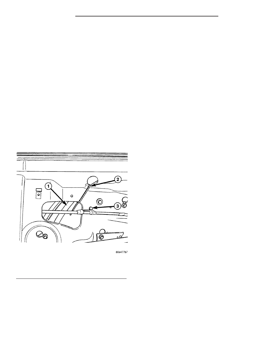
(3) Cut away the tie strap from the outboard reg-

ulator cable. (Fig. 9)

(4) Loosen

screws

attaching

window

regulator

channel and crank housing to door panel (Fig. 4).

(5) Disengage screw and bolt heads from keyhole

slots in door panel.

(6) Loosen bolts attaching window regulator to

door panel.

(7) Disengage regulator from door panel, and

crank housing.

(8) Slide regulator rearward and rotate forward

end of roller channel through access hole in door
panel,

(9) Remove window regulator from door through

access hole in inner panel.

INSTALLATION

(1) Position window regulator and crank housing

on door panel through access hole in door panel.

(2) Tighten bolts attaching window regulator to

door panel.

(3) Engage window regulator bolt heads on chan-

nel to key hole slots in door panel.

(4) Tighten

screw

attaching

window

regulator

channel and crank housing.

(5) Install a new tie strap around the outboard

regulator cable and door inner sheet metal. (Fig. 9)

(6) Position glass to regulator roller channel.
(7) Tighten fasteners attaching door glass to roller

channel.

(8) Install door trim panel.

Fig. 9 TIE STRAP DOOR REGULATOR CABLE

1 - DOOR REGULATOR CABLE
2 - TIE STRAP
3 - WHITE RETAINING CLIP

23 - 36

DOORS - REAR

PL/SRT-4

EXTERIOR

TABLE OF CONTENTS

page

page

BODY STRIPES AND DECALS

REMOVAL

. . . . . . . . . . . . . . . . . . . . . . . . . . . . . 37

INSTALLATION

. . . . . . . . . . . . . . . . . . . . . . . . . 37

COWL GRILLE SCREEN

REMOVAL

. . . . . . . . . . . . . . . . . . . . . . . . . . . . . 37

INSTALLATION

. . . . . . . . . . . . . . . . . . . . . . . . . 37

EXTERIOR NAME PLATES

REMOVAL

. . . . . . . . . . . . . . . . . . . . . . . . . . . . . 38

INSTALLATION

. . . . . . . . . . . . . . . . . . . . . . . . . 38

FRONT END SPLASH SHIELDS

REMOVAL

. . . . . . . . . . . . . . . . . . . . . . . . . . . . . 38

INSTALLATION

. . . . . . . . . . . . . . . . . . . . . . . . . 38

FRONT FENDER

REMOVAL

. . . . . . . . . . . . . . . . . . . . . . . . . . . . . 39

INSTALLATION

. . . . . . . . . . . . . . . . . . . . . . . . . 39

FUEL FILL DOOR

REMOVAL

. . . . . . . . . . . . . . . . . . . . . . . . . . . . . 40

INSTALLATION

. . . . . . . . . . . . . . . . . . . . . . . . . 40

GRILLE

REMOVAL

. . . . . . . . . . . . . . . . . . . . . . . . . . . . . 40

INSTALLATION

. . . . . . . . . . . . . . . . . . . . . . . . . 40

SIDE VIEW MIRROR

REMOVAL

. . . . . . . . . . . . . . . . . . . . . . . . . . . . . 42

INSTALLATION

. . . . . . . . . . . . . . . . . . . . . . . . . 42

SIDE VIEW MIRROR TRIM BEZEL

REMOVAL

. . . . . . . . . . . . . . . . . . . . . . . . . . . . . 42

INSTALLATION

. . . . . . . . . . . . . . . . . . . . . . . . . 42

AIR EXHAUSTER

REMOVAL

. . . . . . . . . . . . . . . . . . . . . . . . . . . . . 42

INSTALLATION

. . . . . . . . . . . . . . . . . . . . . . . . . 42

REAR WHEELHOUSE SPLASH SHIELD

REMOVAL

. . . . . . . . . . . . . . . . . . . . . . . . . . . . . 43

INSTALLATION

. . . . . . . . . . . . . . . . . . . . . . . . . 43

SPOILER

REMOVAL

. . . . . . . . . . . . . . . . . . . . . . . . . . . . . 43

INSTALLATION

. . . . . . . . . . . . . . . . . . . . . . . . . 43

SIDE VIEW MIRROR GLASS

REMOVAL

. . . . . . . . . . . . . . . . . . . . . . . . . . . . . 43

INSTALLATION

. . . . . . . . . . . . . . . . . . . . . . . . . 43

SILL EXTENSION

REMOVAL

. . . . . . . . . . . . . . . . . . . . . . . . . . . . . 44

INSTALLATION

. . . . . . . . . . . . . . . . . . . . . . . . . 44

BODY STRIPES AND DECALS

REMOVAL

(1) Mark reference points before removing.
(2) Using a heat gun gently apply heat in a circu-

lar motion to loosen the adhesive bond.

(3) With your fingernail lift up and peel away

badgeing /tape from panel, using a heat gun as you
go.

(4) Clean off all traces of adhesive from the pan-

el(s) with a general purpose adhesive remover.

INSTALLATION

(1) Clean panel surface with isopropy alcohol.
(2) Remove paper carrier and align badgeing/tape

to reference points or adjacent panel.

(3) Install and press securely, using a plastic

spreader to eliminate all air bubbles.

(4) Remove top protective carrier.
(5) Clean away any reference points.

COWL GRILLE SCREEN

REMOVAL

(1) Release hood latch and open hood.

(2) Remove windshield wiper arms. (Refer to 8 -

ELECTRICAL/WIPERS/WASHERS/WIPER ARMS -
REMOVAL).

(3) Remove the five screws attaching cowl screen

cover to just below windshield flange. (Fig. 1).

(4) Remove cowl plenum to hood weatherstrip, at

the leading edge of cowl cover. Pull weatherstrip
towards the front of the vehicle to remove.

(5) Remove cowl screen windshield seal from upper

edge of the cowl screen cover.

(6) Remove cowl screen cover from the vehicle.

INSTALLATION

(1) Place cowl screen cover into position on vehicle

(Fig. 2).

(2) Start five screws attaching cowl screen cover to

cowl at base of windshield opening.

(3) Install cowl screen windshield seal to upper

edge of the cowl screen.

(4) Push cowl plenum to hood weatherstrip, into

position on the leading edge of cowl screen cover.

(5) Install windshield wiper arms, refer to Group

8K, Windshield Wiper and Washer Systems, for
proper procedures.

(6) Tighten screws attaching cowl screen cover to

cowl at base of windshield opening.

PL/SRT-4

EXTERIOR

23 - 37

(7) Install windshield wiper arms. (Refer to 8 -

ELECTRICAL/WIPERS/WASHERS/WIPER ARMS -
INSTALLATION).

EXTERIOR NAME PLATES

REMOVAL

(1) Mark reference points before removing.
(2) Using a heat gun gently apply heat in a circu-

lar motion to loosen the adhesive bond.

(3) Using a nonmetallic prying device, such as a

plastic or wood trim stick gently pry up at corners
and remove.

(4) Clean off all traces of adhesive or double sided

tape from the panel with a general purpose adhesive
remover.

INSTALLATION

(1) Clean panel surface with isopropy alcohol.
(2) Align badgeing to reference points.
(3) Install and press securely to full adhesive con-

tact

(4) Clean away any reference points.

FRONT END SPLASH SHIELDS

REMOVAL

(1) Hoist and support vehicle on safety stands.

(Refer to LUBRICATION & MAINTENANCE/HOIST-
ING - STANDARD PROCEDURE)

(2) Remove front wheel. (Refer to 22 - TIRES/

WHEELS - REMOVAL)

(3) Remove push-in fasteners attaching splash

shield to frame rail forward of suspension (Fig. 3).

(4) Remove push in fasteners attaching splash

shield to frame rail rearward of suspension.

(5) Remove screws attaching wheelhouse splash

shield to front fender.

(6) Remove splash shield from vehicle.

INSTALLATION

(1) Place splash shield in position on vehicle.
(2) Install screws attaching wheelhouse splash

shield to front fender.

(3) Install push in fasteners attaching splash

shield to frame rail rearward of suspension.

(4) Install push in fasteners attaching splash

shield to frame rail forward of suspension.

(5) Install front wheel.
(6) Lower vehicle.

Fig. 1 COWL SCREEN COVER

1 - RIGHT COWL TOP SCREEN COVER
2 - LEFT COWL TOP SCREEN COVER
3 - COWL SCREEN WINDSHIELD SEAL
4 - SCREWS (5)
5 - COWL PLENUM TO HOOD WEATHERSTRIP

Fig. 2 COWL SCREEN COVER

1 - RIGHT COWL TOP SCREEN COVER
2 - LEFT COWL TOP SCREEN COVER
3 - COWL SCREEN WINDSHIELD SEAL
4 - SCREWS (5)
5 - COWL PLENUM TO HOOD WEATHERSTRIP

23 - 38

EXTERIOR

PL/SRT-4

COWL GRILLE SCREEN (Continued)

FRONT FENDER

REMOVAL

(1) Remove headlamp housing.
(2) Right side of vehicle remove pulley splash

shield.

(3) Remove inner splash shield.
(4) Remove fender to fascia nuts.
(5) Remove fender bolt to lower rocker panel.
(6) Remove fender bolt to lower cowl.
(7) Pull fascia away from fender.
(8) Remove bolts attaching fender to upper rail.
(9) Remove fender from vehicle (Fig. 4).

INSTALLATION

(1) Place fender in position on vehicle.
(2) Start the center upper rail bolt.
(3) From inside engine compartment, install all

the bolts attaching fender to upper rail and tighten.

(4) Install lower cowl panel bolt to fender.
(5) Install rocker panel bolt to fender.
(6) Place fascia into position.
(7) Install fender to fascia nuts.
(8) Install inner splash shield.
(9) Install right side pulley splash shield.
(10) Install headlamp assembly.
(11) Check fender for flush and gap.

Fig. 3 Front Wheelhouse Splash Shield

1 - PUSH IN PLUG
2 - FRONT FASCIA
3 - PULLEY SPLASH SHIELD

4 - FRONT FASCIA
5 - FRONT FENDER SPLASH SHIELD
6 - PULLEY SPLASH SHIELD

PL/SRT-4

EXTERIOR

23 - 39

FRONT END SPLASH SHIELDS (Continued)


Content   ..  386  387  388  389   ..