Dodge Neon / Neon SRT-4. Manual - part 366


  Index      Dodge     Dodge Neon / Neon SRT-4 - service repair manual 2005 year


Search            


Content   ..  364  365  366  367   ..


Dodge Neon / Neon SRT-4. Manual - part 366


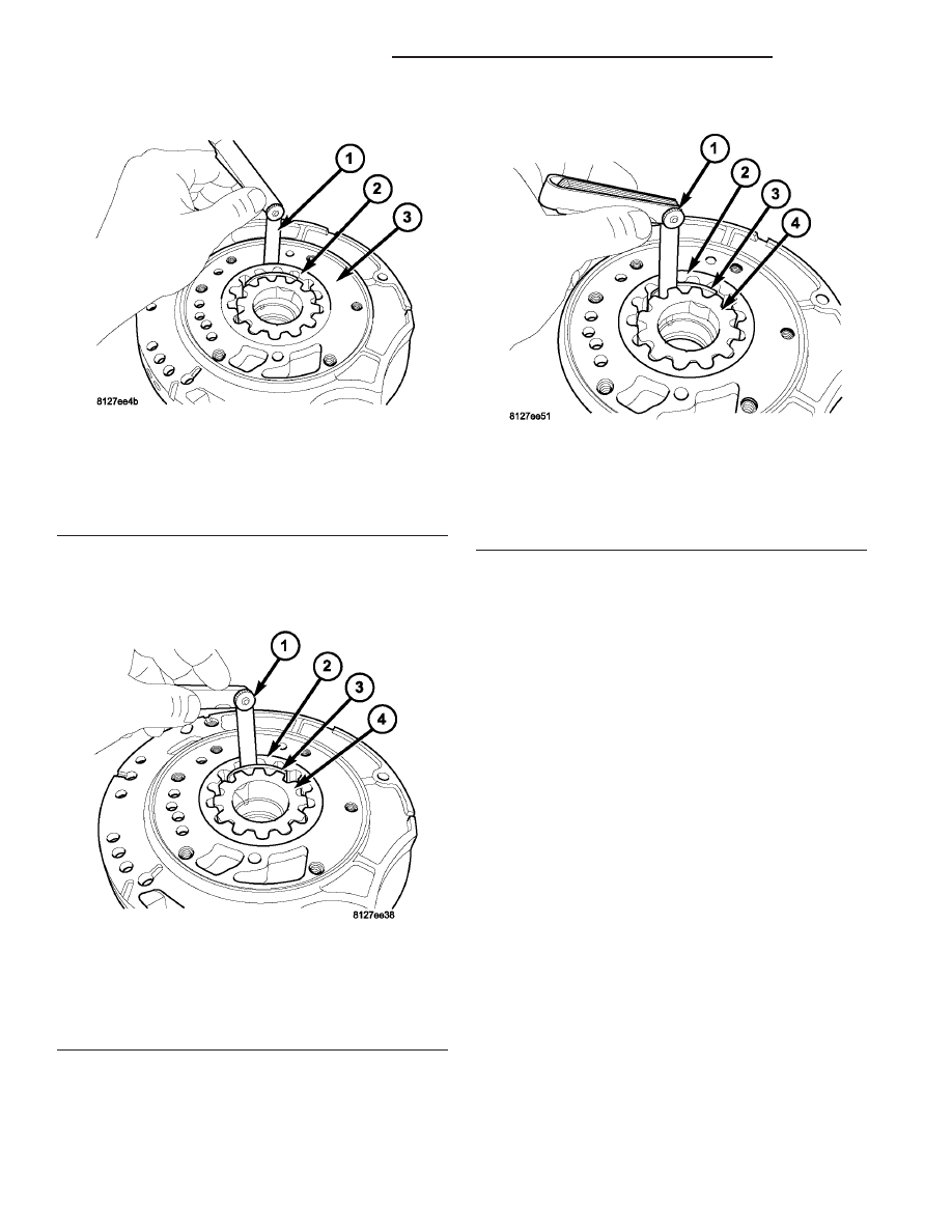
(6) Measure clearance between outer gear and

crescent (Fig. 276). Clearance should be 0.060-0.298
mm (0.0023-0.0117 in.).

(7) Measure clearance between inner gear and

crescent (Fig. 277). Clearance should be 0.093-0.385
mm (0.0036-0.0151 in.).

(8) Position an appropriate piece of Plastigage

across both pump gears.

(9) Align the Plastigage to a flat area on the reac-

tion shaft support housing.

(10) Install the reaction shaft to the pump housing

(Fig. 272). Tighten the bolts to 27 N·m (20 ft. lbs.).

(11) Remove bolts and carefully separate the hous-

ings. Measure the Plastigage following the instruc-
tions supplied.

(12) Clearance between both gear end faces and

the reaction shaft support should be 0.020-0.046 mm
(0.0008-0.0018 in.).

ASSEMBLY

(1) Assemble oil pump as shown in (Fig. 278).

Fig. 275 Measuring Outer Gear-to-Pocket

1 - FEELER GAUGE
2 - OUTER GEAR
3 - PUMP BODY

Fig. 276 Measuring Outer Gear-to-Crescent

1 - FEELER GAUGE
2 - OUTER GEAR
3 - CRESCENT
4 - INNER GEAR

Fig. 277 Measuring Inner Gear-to-Crescent

1 - FEELER GAUGE
2 - OUTER GEAR
3 - CRESCENT
4 - INNER GEAR

21 - 248

40TE AUTOMATIC TRANSAXLE

PL/SRT-4

OIL PUMP (Continued)

(2) Install and torque reaction shaft support-to-oil

pump housing bolts to 28 N·m (20 ft. lbs.) torque
(Fig. 279).

PLANETARY GEARTRAIN

DESCRIPTION

The planetary geartrain is located between the

input clutch assembly and the rear of the transaxle
case. The planetary geartrain consists of two sun
gears, two planetary carriers, two annulus (ring)
gears, and one output shaft (Fig. 280).

OPERATION

The planetary geartrain utilizes two planetary gear

sets that connect the transmission input shaft to the
output shaft. Input and holding clutches drive or lock
different planetary members to change output ratio
or direction.

SEALS - OIL PUMP

REMOVAL

(1) Remove transaxle from vehicle (Refer to 21 -

TRANSMISSION/TRANSAXLE/AUTOMATIC - 41TE
- REMOVAL).

(2) Using Tool C-3981-B, remove oil pump seal

(Fig. 281).

Fig. 278 Oil Pump Assembly

1 - PUMP BODY
2 - OUTER GEAR
3 - INNER GEAR
4 - REACTION SHAFT SUPPORT
5 - SEAL RINGS (4)
6 - REACTION SHAFT
7 - CRESCENT

Fig. 279 Reaction Support-to-Pump Body Bolts

1 - BOLT (6)
2 - PUMP BODY
3 - REACTION SHAFT SUPPORT

Fig. 280 Planetary Geartrain

1 - FRONT SUN GEAR ASSEMBLY
2 - #6 THRUST BEARING
3 - #7 THRUST BEARING
4 - REAR CARRIER/FRONT ANNULUS ASSEMBLY
5 - REAR SUN GEAR
6 - FRONT CARRIER/REAR ANNULUS ASSEMBLY

PL/SRT-4

40TE AUTOMATIC TRANSAXLE

21 - 249

OIL PUMP (Continued)

INSTALLATION

(1) Using Tool C-4193, install oil pump seal (Fig.

282).

(2) Install transaxle to vehicle (Refer to 21 -

TRANSMISSION/TRANSAXLE/AUTOMATIC - 41TE
- INSTALLATION).

SHIFT INTERLOCK CABLE

REMOVAL

(1) Disconnect the battery negative cable.
(2) Loosen set screw and remove knob from shifter

handle (Fig. 283).

(3) Remove the center console assembly as shown

in (Fig. 284).

Fig. 281 Remove Oil Pump Seal

1 - TOOL C-3981–B
2 - OIL PUMP SEAL

Fig. 282 Install Oil Pump Seal

1 - TOOL C-4193
2 - HANDLE TOOL C-4171

Fig. 283 Gearshift Knob Removal/Installation

1 - SHIFTER KNOB
2 - SET SCREW

Fig. 284 Center Console Removal/Installation

1 - CONSOLE
2 - SCREW (4)
3 - SCREW (2)

21 - 250

40TE AUTOMATIC TRANSAXLE

PL/SRT-4

SEALS - OIL PUMP (Continued)

(4) Remove shifter bezel (Fig. 285).

(5) Disconnect the shifter/ignition interlock cable

from the shifter lever and bracket as shown in (Fig.
286). Remove the cable core end from the plastic cam
of the shifter mechanism and release cable from
shifter bracket

(6) Remove the steering column lower cover (Fig.

287).

(7) Remove the steering column upper and lower

shrouds (Fig. 288).

(8) Disconnect the Brake Transmission Shift Inter-

lock (BTSI) solenoid connector from the interlock
cable (Fig. 289).

Fig. 285 Shifter Bezel Removal/Installation

1 - BEZEL
2 - SCREW (4)

Fig. 286 Interlock Cable at Shifter Assembly

1 - INTERLOCK CABLE
2 - SHIFTER ASSEMBLY

Fig. 287 Steering Column Lower Cover

1 - LOWER COVER

Fig. 288 Steering Column Shrouds

1 - UPPER SHROUD
2 - LOWER SHROUD

PL/SRT-4

40TE AUTOMATIC TRANSAXLE

21 - 251

SHIFT INTERLOCK CABLE (Continued)


Content   ..  364  365  366  367   ..