Dodge Neon / Neon SRT-4. Manual - part 291


  Index      Dodge     Dodge Neon / Neon SRT-4 - service repair manual 2005 year


Search            


Content   ..  289  290  291  292   ..


Dodge Neon / Neon SRT-4. Manual - part 291


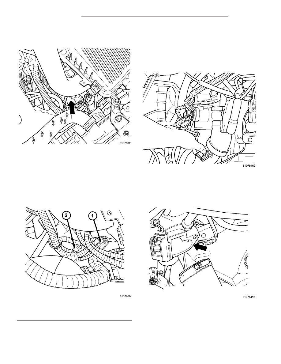
(3) Remove the turbo inlet hose from the air

cleaner housing (Fig. 59).

(4) Remove the makeup air hose for the PCV sys-

tem.

(5) Remove the air cleaner box, refer to the

Engine/Air Cleaner Housing, for more information.

(6) Unlock and disconnect the electrical connectors

from the idle air control motor and throttle position
sensor (Fig. 60).

(7) Disconnect the throttle body inlet hose and

remove from throttle body.

(8) Disconnect the purge hose from the throttle

body.

(9) Remove the throttle cable from the throttle

body lever.

(10) Remove the 2 bolts from the throttle body.
(11) Remove the throttle body (Fig. 61).

(12) Remove the 2 screws for the throttle cable

bracket.

(13) Clean and replace gasket (Fig. 62).

INSTALLATION

INSTALLATION - 2.0L

(1) Install cable’s into throttle cam and clip cable’s

into throttle cable bracket.

Fig. 59 THROTTLE BODY LOCATION 2.4L SRT-4

Fig. 60 IAC & TPS LOCATION - 2.4L SRT-4

1 - Idle Air Control Motor
2 - Throttle Position Sensor

Fig. 61 THROTTLE BODY - 2.4L SRT-4

Fig. 62 MOUNTING SURFACE - 2.4L SRT-4

14 - 46

FUEL INJECTION

PL/SRT-4

THROTTLE BODY (Continued)

(2) Install throttle body onto air cleaner box.

Tighten mounting bolts.

(3) Install and tighten the clamp on throttle body

outlet hose.

(4) Connect the electrical connectors to the throttle

body.

(5) Install the air cleaner element, make sure that

the element is past the lip on the air cleaner box.

(6) Install the air cleaner box cover and tighten

the screws.

(7) Connect the negative battery cable.

INSTALLATION - 1.6L

NOTE: The electrical connector must be pointed
toward the front of vehicle and purge nipple must
be in the up position for proper orientation of the
throttle body (Fig. 57).

(1) Make sure that the mating surfaces for the

throttle body and intake manifold are clean (Fig. 63).

(2) Install the throttle body making sure that the

gasket is installed in the throttle body (Fig. 64) and
(Fig. 65). Align the pin on the manifold gasket to the
pin alignment hole in throttle body, make sure that
the purge nipple is pointed up and electrical connec-
tor is pointed toward the front of vehicle.

(3) Install the 4 bolts to the throttle body (Fig. 57).

Tighten the bolts in a cross pattern to 11.8 N·m (105
in. lbs.).

(4) Connect the vacuum line from the throttle

body.

(5) Connect the electrical connectors at the throttle

body.

(6) Install the clean air duct at the throttle body.
(7) Connect the negative battery cable.

INSTALLATION - 2.4L SRT-4

(1) Clean and replace gasket (Fig. 62).
(2) Install the 2 screws for the throttle cable

bracket and tighten.

(3) Install the throttle body (Fig. 61).
(4) Install the 2 bolts for the throttle body and

tighten.

(5) Install the throttle cable to the throttle body

lever.

(6) Connect the purge hose to the throttle body.
(7) Connect the throttle body inlet hose and

tighten clamp.

(8) Connect and lock the electrical connectors to

the idle air control motor and throttle position sensor
(Fig. 60).

Fig. 63 INTAKE MANIFOLD

Fig. 64 THROTTLE BODY SEAL

Fig. 65 THROTTLE BODY SEAL INSTALLED

PL/SRT-4

FUEL INJECTION

14 - 47

THROTTLE BODY (Continued)

(9) Install the air cleaner box, refer to the Engine/

Air Cleaner Housing, for more information.

(10) Install the makeup air hose for the PCV sys-

tem.

(11) Install the turbo inlet hose to the air cleaner

housing (Fig. 59).

(12) Connect and lock the electrical connector for

the ambient air temperature sensor (Fig. 58).

(13) Connect the negative battery cable.

THROTTLE CONTROL CABLE

REMOVAL

REMOVAL

(1) Remove throttle cable cover or engine cover, if

equipped.

(2) Working from the engine compartment, remove

throttle cable from throttle body cam (Fig. 66) and
(Fig. 67).

(3) Lift the retaining tabs on the cable and slide

cable out of bracket.

(4) From inside the vehicle, hold the throttle pedal

up and remove the cable retainer and cable from
upper end of pedal shaft (Fig. 2).

(5) Remove retainer clip from throttle cable and

grommet at the dashpanel (Fig. 68).

(6) From the engine compartment, pull the throttle

cable and grommet out of the dash panel.

REMOVAL - 2.4L SRT-4

(1) Disconnect the negative battery cable.
(2) Remove the air cleaner box, refer to the

Engine/Air Cleaner Assembly for more information.

(3) Remove the hose from the turbo to air cleaner

box.

(4) Working from the engine compartment, remove

throttle cable from throttle body cam (Fig. 69).

(5) Lift the retaining tabs on the cable and slide

cable out of bracket.

Fig. 66 Throttle Body Cables Attachment to Throttle

Body

Fig. 67 Disconnecting Throttle Cable

Fig. 68 Retainer Clip

14 - 48

FUEL INJECTION

PL/SRT-4

THROTTLE BODY (Continued)

(6) From inside the vehicle, hold the throttle pedal

up and remove the cable retainer and cable from
upper end of pedal shaft.

(7) Remove retainer clip from throttle cable and

grommet at the dashpanel (Fig. 70).

(8) From the engine compartment, pull the throttle

cable and grommet out of the dash panel.

INSTALLATION

INSTALLATION

(1) Install grommet into dashpanel.
(2) From the engine compartment, push the hous-

ing end fitting into the dashpanel grommet.

(3) From the engine compartment, rotate the

throttle lever forward to the wide open position and
install cable clasp (Fig. 67).

(4) Install cable housing (throttle body end) into

the cable mounting bracket on the engine.

(5) Install throttle cable cover.
(6) From inside the vehicle, hold up pedal and feed

throttle cable core wire through hole in upper end of
the pedal shaft. Install cable retainer (Fig. 68).

(7) Install cable retainer clip (Fig. 68).

INSTALLATION

(1) Install grommet into dashpanel.
(2) From the engine compartment, push the hous-

ing end fitting into the dashpanel grommet.

(3) From the engine compartment, rotate the

throttle lever forward to the wide open position and
install cable clasp (Fig. 67).

(4) Install cable housing (throttle body end) into

the cable mounting bracket on the engine.

(5)
(6) From inside the vehicle, hold up pedal and feed

throttle cable core wire through hole in upper end of
the pedal shaft. Install cable retainer (Fig. 68).

(7) Install cable retainer clip (Fig. 68).
(8) Install the hose from the turbo to air cleaner

box at the turbo and tighten clamp.

(9) Install the air cleaner box and install the hose

from the turbo to air cleaner box and tighten clamp.

(10) Connect the negative battery cable.

THROTTLE POSITION SENSOR

DESCRIPTION

The throttle position sensor mounts to the side of

the throttle body (Fig. 71).

The Throttle Position Sensor (TPS) connects to the

throttle blade shaft. The TPS is a variable resistor
that provides the PCM with an input signal (voltage).
The signal represents throttle blade position. As the
position of the throttle blade changes, the resistance
of the TPS changes.

Fig. 69 Throttle Cable

Fig. 70 Retainer Clip

PL/SRT-4

FUEL INJECTION

14 - 49

THROTTLE CONTROL CABLE (Continued)


Content   ..  289  290  291  292   ..