Dodge Neon / Neon SRT-4. Manual - part 290


  Index      Dodge     Dodge Neon / Neon SRT-4 - service repair manual 2005 year


Search            


Content   ..  288  289  290  291   ..


Dodge Neon / Neon SRT-4. Manual - part 290


catalytic convertor efficiency. Also used to establish
the upstream O2 goal voltage (switching point).

REMOVAL

REMOVAL - UPSTREAM 1/1

(1) Raise and support vehicle.
(2) Unplug sensor connector.
(3) Remove sensor using an oxygen sensor crow

foot wrench such as Snap-On tool YA8875 or equiva-
lent (Fig. 45).

(4) After removing the sensor, the exhaust mani-

fold threads must be cleaned with an 18 mm X 1.5 +
6E tap. If reusing the original sensor, coat the sensor
threads with an anti-seize compound such as Loctite

t

771-64 or equivalent.

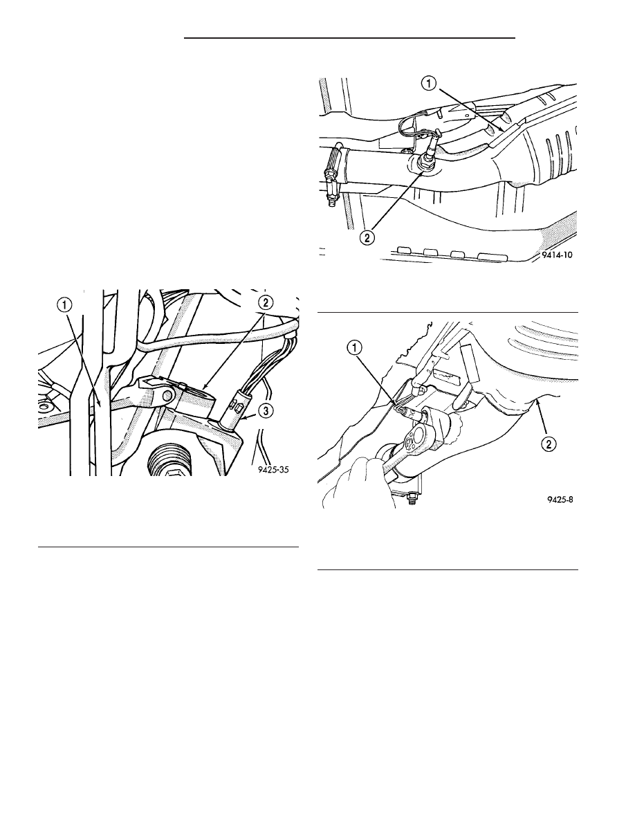
REMOVAL - DOWNSTREAM 1/2

The downstream heated oxygen sensor threads into

the exhaust outlet pipe behind the catalytic convertor
(Fig. 46).

(1) Raise vehicle.
(2) Disconnect electrical connector from harness.
(3) Disconnect sensor electrical harness from clips

along body.

(4) Remove sensor using an oxygen sensor crow

foot wrench such as Snap-On tool YA8875 or equiva-
lent (Fig. 47).

(5) After removing the sensor, the exhaust mani-

fold threads must be cleaned with an 18 mm X 1.5 +
6E tap. If reusing the original sensor, coat the sensor
threads with an anti-seize compound such as Loctite

t

771-64 or equivalent.

REMOVAL - 2.4L TURBO/2.4L SRT-4

(1) Disconnect the negative battery cable.
(2) Unlock and disconnect the electrical connector.

It is on the passenger side near the EVAP purge sole-
noid.

(3) Raise vehicle and support.
(4) Remove sensor (Fig. 48) using an oxygen sen-

sor crow foot wrench such as Snap-On tool YA8875 or
equivalent

INSTALLATION

INSTALLATION - UPSTREAM 1/1

New sensors have compound on the threads and do

not require an additional coating.

Fig. 45 Upstream Heated Oxygen Sensor Removal/

Installation

1 - EXHAUST PIPE FLANGE
2 - CROW FOOT WRENCH
3 - UPSTREAM OXYGEN SENSOR

Fig. 46 Downstream Heated Oxygen Sensor

1 - CATALYTIC CONVERTOR
2 - DOWNSTREAM OXYGEN SENSOR

Fig. 47 Downstream Heated Oxygen Sensor

Removal/Installation

1 - DOWNSTREAM HEATED OXYGEN SENSOR
2 - CATALYTIC CONVERTOR

14 - 42

FUEL INJECTION

PL/SRT-4

O2 SENSOR (Continued)

(1) Install sensor using an oxygen sensor crow foot

wrench such as Snap-On tool YA8875 or equivalent
(Fig. 45). Tighten the sensor to 28 N·m (20 ft. lbs.)
torque.

(2) Plug sensor connector.
(3) Lower vehicle.

INSTALLATION - DOWNSTREAM 1/2

The downstream heated oxygen sensor threads into

the exhaust outlet pipe behind the catalytic convertor
(Fig. 46).

New sensors have compound on the threads and do

not require an additional coating.

(1) Install sensor using an oxygen sensor crow foot

wrench such as Snap-On tool YA8875 or equivalent
(Fig. 47). Tighten the sensor to 28 N·m (20 ft. lbs.)
torque.

(2) Connect sensor electrical harness from clips

along body.

(3) Connect electrical connector to harness.
(4) Lower vehicle.

INSTALLATION - 2.4L TURBO/2.4L SRT-4

(1) Install O2 sensor (Fig. 48) using an oxygen

sensor crow foot wrench such as Snap-On tool
YA8875 or equivalent and tighten to N·m 28 (20 ft.
lbs.).

(2) Route O2 sensor wire (Fig. 49) above the heat

shield for the generator and away from the exhaust
manifold.

(3) Lower vehicle.
(4) Connect and lock the O2S connector. It is on

the passenger side near the EVAP purge solenoid.

(5) Connect the negative battery cable.

THROTTLE BODY

REMOVAL

REMOVAL - 2.0L

(1) Disconnect the negative battery cable (Fig. 50).

(2) Remove the air cleaner box cover.

Fig. 48 UPSTREAM O2 SENSOR- 2.4L TURBO

Fig. 49 O2 WIRE ROUTING

1 - O2 Sensor Electrical Connector
2 - Wire routing
3 - O2 Sensor
4 - Heat Shield
5 - Generator

Fig. 50 Battery Negative Cable

PL/SRT-4

FUEL INJECTION

14 - 43

O2 SENSOR (Continued)

(3) Remove the air cleaner element (Fig. 51). Pull

up on element, past the lip in the box, to remove it
from the air cleaner box.

(4) Disconnect the electrical connection at the

throttle body.

(5) Loosen the clamp on throttle body outlet hose.
(6) Remove the bolts holding the throttle body to

the air cleaner box (Fig. 52).

(7) Remove cable’s from throttle body cam (Fig. 53)

and (Fig. 54).

REMOVAL - 1.6L

If any components on the throttle body are bad, the

throttle body has to be replaced, except the seal to
the intake manifold (Fig. 55) or (Fig. 56). There is no
serviceable component on the throttle body.

NOTE: The electrical connector must be pointed
toward the front of vehicle and purge nipple must
be in the up position for proper orientation of the
throttle body (Fig. 57).

(1) Disconnect the negative battery cable.
(2) Remove the throttle clean air duct at the throt-

tle body.

(3) Disconnect the electrical connector at the throt-

tle body.

Fig. 51 Air Cleaner Element

1 - LIP

Fig. 52 Throttle body bolts

Fig. 53 Disconnecting Throttle Cable

Fig. 54 Transmission Kickdown Cable Connector

14 - 44

FUEL INJECTION

PL/SRT-4

THROTTLE BODY (Continued)

(4) Disconnect the vacuum line from the throttle

body.

(5) Remove the 4 bolts from the throttle body (Fig.

57).

(6) Remove the throttle body.

REMOVAL - 2.4L SRT-4

(1) Disconnect the negative battery cable.
(2) Unlock and disconnect the electrical connector

for the ambient air temperature sensor (Fig. 58).

Fig. 55 THROTTLE BODY FRONT

Fig. 56 THROTTLE BODY BACK

Fig. 57 THROTTLE BODY

Fig. 58 AMBIENT AIR TEMP. SENSOR - 2.4L SRT-4

PL/SRT-4

FUEL INJECTION

14 - 45

THROTTLE BODY (Continued)


Content   ..  288  289  290  291   ..