Dodge Neon / Neon SRT-4. Manual - part 242


  Index      Dodge     Dodge Neon / Neon SRT-4 - service repair manual 2005 year


Search            


Content   ..  240  241  242  243   ..


Dodge Neon / Neon SRT-4. Manual - part 242


(11) Remove right engine mount to engine mount

bracket through bolt (Fig. 97).

(12) Lower engine enough with jack to remove

lower engine mount bracket bolt (Fig. 98).

(13) Raise engine with jack to allow engine-to-body

clearance for engine mount bracket removal.

(14) Remove fasteners securing power steering

pump to engine mount bracket. Do Not disconnect
lines from pump.

(15) Remove the two remaining bolts securing

engine mount bracket to engine. Remove engine
mount bracket (Fig. 98).

INSTALLATION

(1) Position engine mount bracket to its mounting

location. Hand start the upper two bolts of the
engine mount bracket (Fig. 98).

(2) Lower engine with jack.
(3) Install

lower

engine

mount

bracket

bolt.

Tighten bolt to 61 N·m (45 ft. lbs.) (Fig. 98).

(4) Raise engine with jack.
(5) Tighten upper engine mount bracket bolts to 61

N·m (45 ft. lbs.) (Fig. 98).

(6) Install power steering pump fasteners.
(7) Lower engine with jack.
(8) Install right engine mount to engine mount

bracket through bolt. Tighten bolt to 118 N·m (87 ft.
lbs.) (Fig. 97).

(9) Install mount bolt access plug (Fig. 96).
(10) Remove jack from under engine.
(11) Raise vehicle on hoist.
(12) Install lower torque strut (Refer to 9 -

ENGINE/ENGINE MOUNTING/TORQUE STRUT -
INSTALLATION).

(13) Install power steering/air conditioning com-

pressor drive belt (Refer to 7 - COOLING/ACCES-
SORY DRIVE/DRIVE BELTS - INSTALLATION).

(14) Install accessory drive belt splash shield (Fig.

96).

(15) Lower vehicle.
(16) Install upper torque strut (Refer to 9 -

ENGINE/ENGINE MOUNTING/TORQUE STRUT -
INSTALLATION).

(17) Install fastener securing ground strap to

engine mount bracket.

(18) Connect negative battery cable.
(19) Perform torque strut adjustment procedure

(Refer

to

9

-

ENGINE/ENGINE

MOUNTING/

TORQUE STRUT - ADJUSTMENTS).

RIGHT MOUNT

REMOVAL

(1) Remove engine mount bracket (Refer to 9 -

ENGINE/ENGINE MOUNTING/ENGINE MOUNT
BRACKET - REMOVAL).

NOTE: The right engine mount attaching holes are
slightly oversize to compensate for manufacturing
tolerances. The mount has been set at the manufac-
turing plant for proper powertrain alignment. There-
fore, it is necessary to mark the position of the
mount before the attaching bolts are loosened.

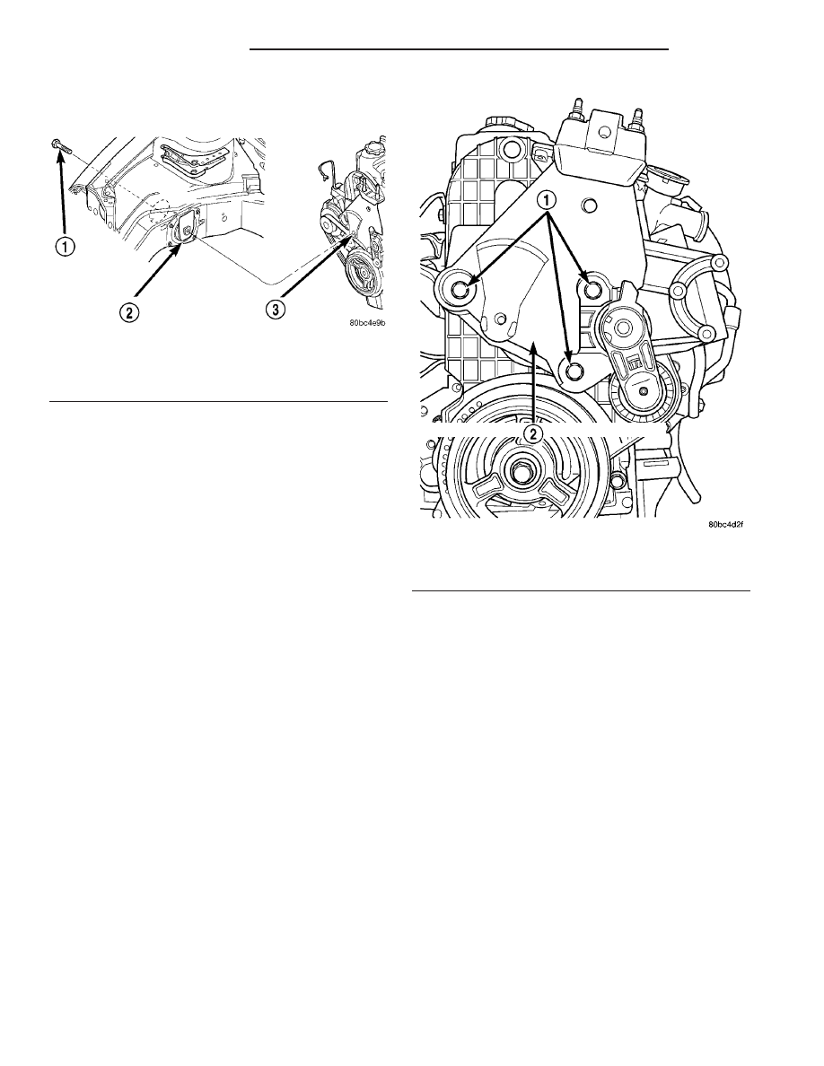
Fig. 97 Engine Mount to Bracket

1 - THROUGH BOLT
2 - RIGHT ENGINE MOUNT
3 - ENGINE MOUNT BRACKET

Fig. 98 Engine Mount Bracket Assembly

1 - BOLTS
2 - ENGINE MOUNT BRACKET ASSEMBLY

9 - 62

ENGINE 2.0L SOHC

PL/SRT-4

ENGINE MOUNT BRACKET (Continued)

(2) Using a permanent ink marker or equivalent,

mark the position of engine mount to the body frame
rail.

(3) Remove bolts attaching mount to body (Fig.

99).

(4) Lower engine with jack.
(5) Postion right engine mount into timing belt

cover hole (Fig. 100).

(6) Raise engine with jack.
(7) Remove mount between engine and body frame

rail. Mount removal may require engine position to
be raised or lowered to allow mount removal clear-
ance.

INSTALLATION

(1) Postion right engine mount into timing belt

cover hole (Fig. 100).

(2) Lower engine with jack.
(3) Position the mount into the original position on

body frame rail (Fig. 99).

NOTE: Engine mount must be installed in the origi-
nal position on body frame rail. If mount was not
marked or frame rail was replaced, perform the fol-
lowing procedure.

(4) Perform the following procedure if mount posi-

tion was not previously marked or the frame rail was
replaced:

(a) Insert the new mount loosely in frame rail.
(b) Align the four holes in the mount with the

mating holes in the rail such that the holes are
concentric (frame rail holes centered in the mount
holes).

(c) Using a permanent ink marker or equivalent,

mark the position of engine mount to the body
frame rail while maintaining mounting hole con-
centricity.
(5) Ensure the mount maintains originally marked

position and install mount bolts. Tighten bolts to 28
N·m (250 in. lbs.) (Fig. 99).

(6) Raise engine with jack.
(7) Install the engine mount bracket (Refer to 9 -

ENGINE/ENGINE MOUNTING/ENGINE MOUNT
BRACKET - INSTALLATION).

(8) Perform torque strut adjustment procedure

(Refer

to

9

-

ENGINE/ENGINE

MOUNTING/

TORQUE STRUT - ADJUSTMENTS).

Fig. 99 Engine Mount—Right

1 - SNUBBER PAD
2 - RIGHT ENGINE MOUNT
3 - BOLTS

Fig. 100 Right Engine Mount - Removal/Installation

1 - TIMING BELT COVER HOLE
2 - RIGHT ENGINE MOUNT

PL/SRT-4

ENGINE 2.0L SOHC

9 - 63

RIGHT MOUNT (Continued)

TORQUE STRUT

REMOVAL

UPPER TORQUE STRUT

(1) Remove bolts attaching strut to shock tower

bracket and engine mount bracket (Fig. 102).

(2) Remove the upper torque strut.

LOWER TORQUE STRUT

(1) Raise vehicle on hoist.
(2) Remove accessory drive belt splash shield.
(3) Remove pencil strut (Fig. 101).
(4) Remove bolts attaching lower strut to cross-

member and strut bracket (Fig. 102).

(5) Remove lower torque strut.

INSTALLATION

UPPER TORQUE STRUT

(1) Position the upper torque strut into mounting

locations (Fig. 102).

(2) Install the mounting bolts and perform the

torque strut adjustment procedure (Refer to 9 -

ENGINE/ENGINE MOUNTING/TORQUE STRUT -
ADJUSTMENTS).

Fig. 101 Pencil Strut

1 - NUT
2 - PENCIL STRUT
3 - NUT
4 - FLAT WASHER
5 - LOWER TORQUE STRUT

Fig. 102 Torque Struts - Upper / Lower

1 - BOLTS
2 - ENGINE MOUNT BRACKET
3 - TORQUE STRUT BRACKET
4 - UPPER TORQUE STRUT

5 - CROSSMEMBER
6 - LOWER TORQUE STRUT
7 - BOLTS
8 - RIGHT FENDER

9 - 64

ENGINE 2.0L SOHC

PL/SRT-4

LOWER TORQUE STRUT

(1) Position lower torque strut into mounting loca-

tions (Fig. 102).

(2) Install mounting bolts and perform torque

strut adjustment procedure (Refer to 9 - ENGINE/
ENGINE MOUNTING/TORQUE STRUT - ADJUST-
MENTS).

(3) Install pencil stut (Fig. 101).
(4) Install accessory drive belt splash shield and

lower vehicle.

ADJUSTMENTS

ENGINE TORQUE STRUT ADJUSTMENT

The upper and lower torque struts need to be

adjusted together to assure proper engine positioning
and engine mount loading. Whenever a torque strut
bolt(s) is loosened, this procedure must be performed.

(1) Loosen the upper and lower torque strut

attaching bolt at the suspension crossmember and
shock tower bracket.

(2) The engine position may now be adjusted by

positioning a suitable floor jack on the forward edge
of the transmission bell housing (Fig. 103).

NOTE: The floor jack must be positioned as shown
in (Fig. 103) to prevent minimal upward lifting of the
engine.

(3) With the engine supported, remove the upper

and lower torque strut attachment bolt(s) at shock
tower bracket and suspension crossmember (Fig.
102). Verify that the torque struts are free to move
within the shock tower bracket and crossmember.
Reinstall the torque strut bolt(s), but do not tighten.

(4) Carefully apply upward force, allowing the

upper engine to rotate rearward until the distance
between the center of the rearmost attaching stud on
the engine mount bracket (point “A”) and the center
of the hole for the washer hose clip on the shock
tower bracket (point “B”) is 119 mm (4.70 in.) (Fig.
104).

(5) With the engine held at the proper position,

tighten both the upper and lower torque strut bolts
to 118 N·m (87 ft. lbs.) (Fig. 102).

(6) Remove the floor jack.

Fig. 103 Floor Jack Positioning

1 - WOOD BLOCK
2 - FLOOR JACK

Fig. 104 Engine Position Measurement

PL/SRT-4

ENGINE 2.0L SOHC

9 - 65

TORQUE STRUT (Continued)


Content   ..  240  241  242  243   ..