Dodge Neon / Neon SRT-4. Manual - part 243


  Index      Dodge     Dodge Neon / Neon SRT-4 - service repair manual 2005 year


Search            


Content   ..  241  242  243  244   ..


Dodge Neon / Neon SRT-4. Manual - part 243


LUBRICATION

DESCRIPTION

The lubrication system is a full-flow filtration,

pressure feed type. The oil pump (Fig. 105) is
mounted in the front engine cover and driven by the
crankshaft.

OPERATION

Refer to (Fig. 106) for lubrication system flow.

Engine oil is drawn up through the pickup tube and
is pressurized by the oil pump and routed through
the full-flow filter to the main oil gallery running the
length of the cylinder block. A diagonal hole in each
bulkhead feeds oil to each main bearing. Drilled pas-
sages within the crankshaft route oil from the main
bearing journals to the connecting rod journals. A
vertical hole at the number five bulkhead routes
pressurized oil through a restrictor up into the cylin-
der head. The restrictor that is integral to the cylin-
der head gasket, provides increased oil flow to the
main gallery. The rocker shafts route oil to the rocker

arms/hydraulic lash adjusters. Oil returning to the
oil pan from the pressurized components supplies
lubrication to the valve stems. The cylinder bores
and wrist pins are splash lubricated from directed
slots on the connecting rod thrust collar.

DIAGNOSIS AND TESTING

ENGINE OIL LEAK INSPECTION

Begin with a thorough visual inspection of the

engine, particularly at the area of the suspected leak.
If an oil leak source is not readily identifiable, the
following steps should be followed:

(1) Do not clean or degrease the engine at this

time because some solvents may cause rubber to
swell, temporarily stopping the leak.

(2) Add an oil soluble dye (use as recommended by

manufacturer). Start the engine and let idle for
approximately 15 minutes. Check the oil dipstick to
make sure the dye is thoroughly mixed as indicated
with a bright yellow color under a black light.

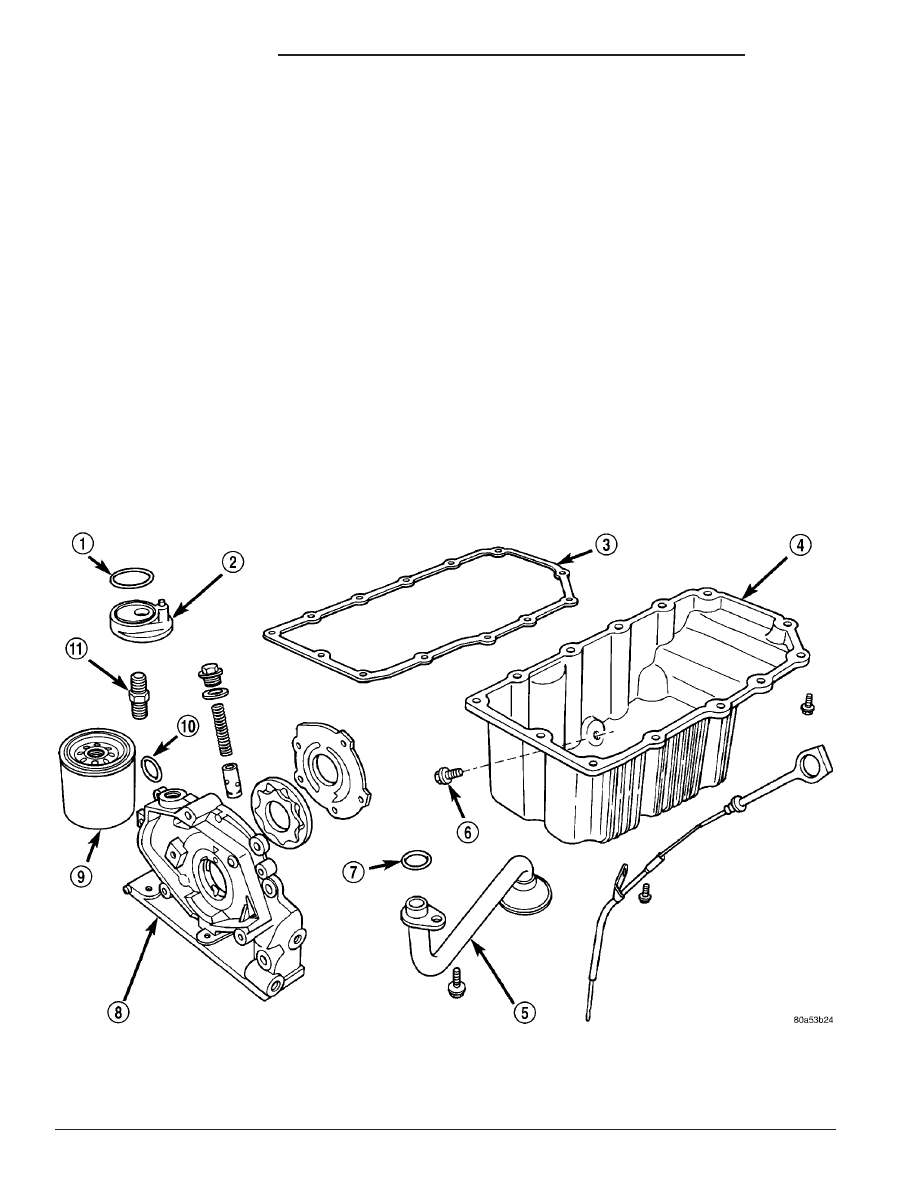
Fig. 105 Engine Lubrication Components

1 - O-RING

7 - O-RING

2 - OIL FILTER ADAPTER

8 - OIL PUMP BODY

3 - OIL PAN GASKET

9 - FILTER

4 - OIL PAN

10 - O-RING

5 - OIL PICK-UP TUBE

11 - NIPPLE

6 - DRAIN PLUG

9 - 66

ENGINE 2.0L SOHC

PL/SRT-4

(3) Using a black light, inspect the entire engine

for fluorescent dye, particularly at the suspected area
of oil leak. If the oil leak is found and identified,
repair as necessary.

(4) If dye is not observed, drive the vehicle at var-

ious speeds for approximately 24 km (15 miles), and
repeat inspection.

(5) If the oil leak source is not positively

identified at this time, proceed with the air leak
detection test method as follows:

• Disconnect the fresh air hose (make-up air) at

the cylinder head cover and plug or cap the nipple on
the cover.

• Remove the PCV valve hose from the cylinder

head cover. Cap or plug the PCV valve nipple on the
cover.

• Attach an air hose with pressure gauge and reg-

ulator to the dipstick tube.

CAUTION: Do not subject the engine assembly to
more than 20.6 kpa (3 PSI) of test pressure.

• Gradually apply air pressure from 1 psi to 2.5

psi maximum while applying soapy water at the sus-
pected source. Adjust the regulator to the suitable
test pressure that provides the best bubbles which
will pinpoint the leak source. If the oil leak is
detected and identified, repair per service manual
procedures.

• If the leakage occurs at the crankshaft rear oil

seal area, refer to the section, Inspection for Rear
Seal Area Leak.

(6) If no leaks are detected, turn off the air supply.

Remove the air hose, all plugs, and caps. Install the

PCV valve and fresh air hose (make-up air). Proceed
to next step.

(7) Clean the oil off the suspect oil leak area using

a suitable solvent. Drive the vehicle at various
speeds approximately 24 km (15 miles). Inspect the
engine for signs of an oil leak by using a black light.

NOTE: If oil leakage is observed at the dipstick tube
to block location; remove the tube, clean and reseal
using Mopar

T

Stud & Bearing Mount (press fit tube

applications only), and for O-ring style tubes,
remove tube and replace the O-ring seal.

INSPECTION FOR REAR SEAL AREA LEAKS

Since it is sometimes difficult to determine the

source of an oil leak in the rear seal area of the
engine, a more involved inspection is necessary. The
following steps should be followed to help pinpoint
the source of the leak.

If the leakage occurs at the crankshaft rear oil seal

area:

(1) Disconnect the battery.
(2) Raise the vehicle.
(3) Remove torque converter or clutch housing

cover and inspect rear of block for evidence of oil.
Use a black light to check for the oil leak. If a leak is
present in this area, remove transmission for further
inspection.

(a) Circular spray pattern generally indicates

seal leakage or crankshaft damage.

(b) Where leakage tends to run straight down,

possible causes are a porous block, oil gallery cup
plug, bedplate to cylinder block mating surfaces
and seal bore. See proper repair procedures for
these items.
(4) If no leaks are detected, pressurize the crank-

case as previously described.

CAUTION: Do not exceed 20.6 kPa (3 psi).

(5) If the leak is not detected, very slowly turn the

crankshaft and watch for leakage. If a leak is
detected between the crankshaft and seal while
slowly turning the crankshaft, it is possible the
crankshaft seal surface is damaged. The seal area on
the crankshaft could have minor nicks or scratches
that can be polished out with emery cloth.

CAUTION: Use extreme caution when crankshaft
polishing is necessary to remove minor nicks and
scratches. The crankshaft seal flange is especially
machined to complement the function of the rear oil
seal.

Fig. 106 Engine Lubrication System

PL/SRT-4

ENGINE 2.0L SOHC

9 - 67

LUBRICATION (Continued)

(6) For bubbles that remain steady with shaft

rotation, no further inspection can be done until dis-
assembled.

(7) After the oil leak root cause and appropriate

corrective action have been identified, replace compo-
nent(s) as necessary.

DIAGNOSIS AND TESTING - CHECKING
ENGINE OIL PRESSURE

Check oil pressure using a gauge at oil pressure

switch location.

(1) Remove the oil pressure switch (Refer to 9 -

ENGINE/LUBRICATION/OIL PRESSURE SENSOR/
SWITCH - REMOVAL).

(2) Install oil pressure test gauge, Special Tool

C-3292 with Adapter 8406. For Special Tool identifi-
cation, (Refer to 9 - ENGINE - SPECIAL TOOLS).

CAUTION: If oil pressure is 0 at idle, Do Not Run
engine at 3000 RPM.

(3) Warm engine to normal operating temperature.
(4) Monitor gauge readings at idle and 3000 rpm.

For specifications (Refer to 9 - ENGINE - SPECIFI-
CATIONS).

OIL

STANDARD PROCEDURE

ENGINE OIL LEVEL CHECK

The best time to check engine oil level is after it

has sat overnight, or if the engine has been running,
allow the engine to be shut off for at least 5 minutes
before checking oil level.

Checking the oil while the vehicle is on level

ground will improve the accuracy of the oil level
reading. Remove dipstick (Fig. 107)and observe oil
level. Add oil only when the level is at or below the
ADD mark (Fig. 108).

Fig. 107 Dipstick and Engine Oil Fill Locations

1 - ENGINE OIL FILL
2 - ENGINE COOLANT RECOVERY CONTAINER

3 - ENGINE OIL DIPSTICK
4 - COOLING SYSTEM PRESSURE CAP

Fig. 108 Oil Level

1 - ENGINE OIL LEVEL DIPSTICK

9 - 68

ENGINE 2.0L SOHC

PL/SRT-4

LUBRICATION (Continued)

ENGINE OIL AND FILTER CHANGE

Change engine oil at mileage and time intervals

described in the Maintenance Schedule. (Refer to
LUBRICATION

&

MAINTENANCE/MAINTE-

NANCE SCHEDULES - DESCRIPTION)

WARNING: NEW OR USED ENGINE OIL CAN BE
IRRITATING TO THE SKIN. AVOID PROLONGED OR
REPEATED SKIN CONTACT WITH ENGINE OIL.
CONTAMINANTS IN USED ENGINE OIL, CAUSED BY
INTERNAL COMBUSTION, CAN BE HAZARDOUS TO
YOUR HEALTH. THOROUGHLY WASH EXPOSED
SKIN WITH SOAP AND WATER. DO NOT WASH
SKIN WITH GASOLINE, DIESEL FUEL, THINNER, OR
SOLVENTS, HEALTH PROBLEMS CAN RESULT. DO
NOT POLLUTE, DISPOSE OF USED ENGINE OIL
PROPERLY. CONTACT YOUR DEALER OR GOVERN-
MENT AGENCY FOR LOCATION OF COLLECTION
CENTER IN YOUR AREA.

Run engine until achieving normal operating tem-

perature.

(1) Position the vehicle on a level surface and turn

engine off.

(2) Remove oil fill cap (Fig. 107).
(3) Raise vehicle on hoist.
(4) Place a suitable oil collecting container under

oil pan drain plug (Fig. 109).

(5) Remove oil pan drain plug and allow oil to

drain into collecting container. Inspect drain plug
threads for stretching or other damage. Replace
drain plug and gasket if damaged.

(6) Remove oil filter (Refer to 9 - ENGINE/LUBRI-

CATION/OIL FILTER - REMOVAL).

(7) Install and tighten oil pan drain plug to 27

N·m (20 ft. lbs.).

(8) Install new oil filter (Refer to 9 - ENGINE/LU-

BRICATION/OIL FILTER - INSTALLATION).

(9) Lower vehicle and fill crankcase with specified

type and amount of engine oil (Refer to LUBRICA-
TION

&

MAINTENANCE/FLUID

TYPES

-

DESCRIPTION).

(10) Install oil fill cap.
(11) Start engine and inspect for leaks.
(12) Stop engine and inspect oil level.

NOTE: Care should be exercised when disposing
used engine oil after it has been drained from a
vehicle engine. Refer to the WARNING listed above.

OIL FILTER

REMOVAL

CAUTION: When servicing the oil filter (Fig. 109),
avoid deforming the filter. Use an appropriate oil fil-
ter removing tool. Position filter wrench strap close
the seam at the base of the filter. The oil filter seam
that joins the can to the base, is reinforced by the
base plate.

(1) Turn filter counterclockwise to remove (Fig.

109).

INSTALLATION

(1) Clean and check the filter mounting surface.

The surface must be smooth, flat and free of debris
or old pieces of rubber.

(2) Lubricate new filter gasket.
(3) Screw filter on until gasket contacts base (Fig.

109). Tighten to 11 N·m (8 ft. lbs.).

Fig. 109 Engine Oil Filter

1 - OIL FILTER
2 - DRAIN PLUG

PL/SRT-4

ENGINE 2.0L SOHC

9 - 69

OIL (Continued)


Content   ..  241  242  243  244   ..