Dodge Neon / Neon SRT-4. Manual - part 241


  Index      Dodge     Dodge Neon / Neon SRT-4 - service repair manual 2005 year


Search            


Content   ..  239  240  241  242   ..


Dodge Neon / Neon SRT-4. Manual - part 241


VIBRATION DAMPER

REMOVAL

(1) Raise vehicle on a hoist and remove accessory

drive belt splash shield.

(2) Remove accessory drive belts (Refer to 7 -

COOLING/ACCESSORY

DRIVE/DRIVE

BELTS

-

REMOVAL).

(3) Remove

crankshaft

vibration

damper

bolt.

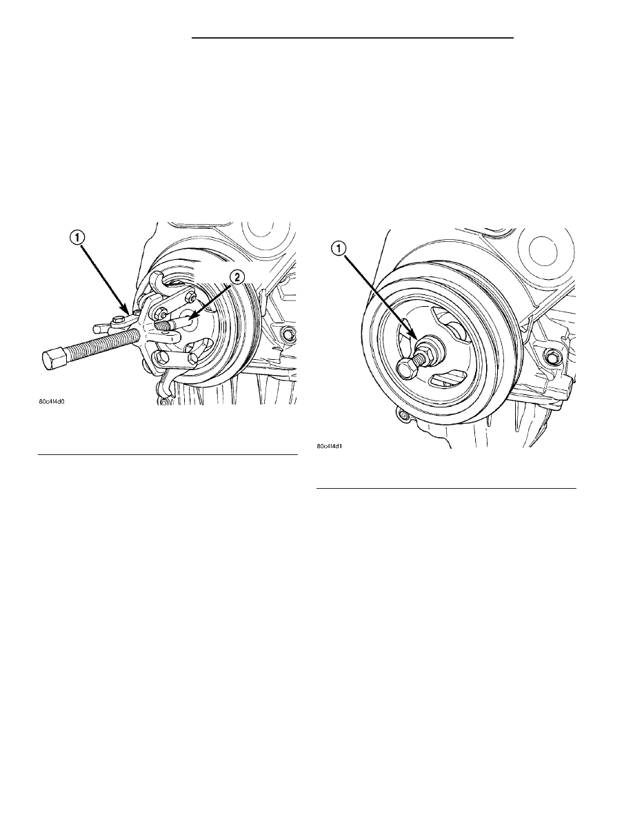
Remove damper using the large side of Special Tool
1026 and insert 6827-A (Fig. 87).

INSTALLATION

NOTE: Lubricate the threads of the M12 1.75 x 150
mm bolt using Mopar

T

Nickel Anti-seize Compound

or equivalent, before beginning to press the damper
on.

(1) Install

crankshaft

vibration

damper

using

M12–1.75 x 150 mm bolt, washer, thrust bearing and
nut from Special Tool 6792 (Fig. 88).

(2) Apply Mopar

t Lock & Seal Adhesive (Medium

Strength Threadlocker) to vibration damper bolt.
Tighten vibration damper bolt to 136 N·m (100 ft.
lbs.).

(3) Install accessory drive belts (Refer to 7 -

COOLING/ACCESSORY

DRIVE/DRIVE

BELTS

-

INSTALLATION).

(4) Install the accessory drive belt splash shield

and lower vehicle.

Fig. 87 Crankshaft Damper—Removal

1 - SPECIAL TOOL 1026 3 - JAW PULLER
2 - SPECIAL TOOL 6827A INSERT

Fig. 88 Crankshaft Damper—Installation

1 - SPECIAL TOOL 6792

9 - 58

ENGINE 2.0L SOHC

PL/SRT-4

ENGINE MOUNTING

DESCRIPTION

The engine mounting system (Fig. 89) and (Fig. 90)

consist of a four-point system utilizing two load-car-
rying mounts and two torque struts. The load-carry-
ing mounts are located on each frame rail. The right
mount is a hydro-elastic mount and left mount is a
conventional elastomeric isolator. The two torque
controlling struts are attached at the front of the
engine,

straddling

the

right

side

load-carrying

mount. The upper torque strut connects to the sus-
pension strut tower and the lower torque strut con-
nects to the suspension crossmember.

Fig. 89 Engine Mounting - Right Side

1 - BOLTS
2 - ENGINE MOUNT BRACKET
3 - TORQUE STRUT BRACKET
4 - UPPER TORQUE STRUT

5 - CROSSMEMBER
6 - LOWER TORQUE STRUT
7 - BOLTS
8 - RIGHT FENDER

Fig. 90 Engine Mounting - Left Side

1 - MOUNT
2 - TRANSAXLE

PL/SRT-4

ENGINE 2.0L SOHC

9 - 59

LEFT MOUNT

REMOVAL

(1) Raise vehicle approximately 30.5 cm (12 in.) on

hoist

(2) Remove air cleaner assembly (Fig. 91).
(3) Remove battery and tray.
(4) Support transaxle with a suitable jack.

(5) Remove left front wheel.
(6) Remove left splash shield.
(7) Remove through bolt access plug at left side

outer frame rail.

(8) Remove mount through bolt (Fig. 92).
(9) Disconnect

transaxle

shift

cable

from

left

mount and transaxle linkage.

(10) Remove left mount bracket to body frame rail

fasteners (Fig. 93).

(11) Remove mount attaching bolts (Fig. 94) or

(Fig. 95).

(12) Remove mount.

Fig. 91 Air Cleaner Assembly

1 - AIR CLEANER ASSY.
2 - THROTTLE BODY DUCT

Fig. 92 Left Mount Through Bolt

1 - MOUNT BRACKET
2 - BOLT
3 - MOUNT

Fig. 93 Left Mount Bracket

1 - MOUNT BRACKET
2 - BODY FRAME RAIL

Fig. 94 Left Mount (Automatic Transaxle)

1 - MOUNT
2 - TRANSAXLE

9 - 60

ENGINE 2.0L SOHC

PL/SRT-4

INSTALLATION

(1) Install mount and attaching bolts (Fig. 94)or

(Fig. 95). Tighten bolts to 68 N·m (50 ft. lbs.).

(2) Install engine mount bracket to body frame rail

and tighten fasteners to 28 N·m (250 in. lbs.) (Fig.
93).

(3) Position engine/transaxle for installation of

through bolt. Install and tighten through bolt to 118
N·m (87 ft. lbs.) (Fig. 92).

(4) Remove jack from under transaxle.
(5) Install through bolt access plug at left side

outer frame rail.

(6) Install left splash shield and wheel.
(7) Connect transaxle shift cable to engine mount

and transaxle linkage.

(8) Install battery tray and battery.
(9) Install air cleaner assembly (Fig. 91).
(10) Lower vehicle.

ENGINE MOUNT BRACKET

REMOVAL

(1) Disconnect negative battery cable.
(2) Remove fastener securing ground strap to

engine mount bracket.

(3) Remove upper torque strut (Refer to 9 -

ENGINE/ENGINE MOUNTING/TORQUE STRUT -
REMOVAL).

(4) Remove power steering/air conditioning com-

pressor drive belt (Refer to 7 - COOLING/ACCES-
SORY DRIVE/DRIVE BELTS - REMOVAL).

(5) Raise vehicle on hoist.
(6) Remove accessory drive belt splash shield (Fig.

96).

(7) Remove lower torque strut (Refer to 9 -

ENGINE/ENGINE MOUNTING/TORQUE STRUT -
REMOVAL).

(8) Lower vehicle.
(9) Position

a

jack

under

engine.

Raise

jack

enough to support engine weight.

(10) Remove engine mount through bolt access

plug (Fig. 96)

Fig. 95 Left Mount (Manual Transaxle)

1 - MOUNT
2 - TRANSAXLE

Fig. 96 Engine Mount Bolt Access Plug

1 - CRANKSHAFT BOLT ACCESS PLUG
2 - RIGHT MOUNT BOLT ACCESS PLUG
3 - FASCIA
4 - SPLASH SHIELD

PL/SRT-4

ENGINE 2.0L SOHC

9 - 61

LEFT MOUNT (Continued)


Content   ..  239  240  241  242   ..