Dodge Neon / Neon SRT-4. Manual - part 238
(17) Using a permanent ink or paint marker, iden-
tify cylinder number on each connecting rod cap (Fig.
55).
CAUTION: DO NOT use a number stamp or a punch
to mark connecting rods. Damage to connecting
rod could occur.
(18) Remove all connecting rod bolts and caps.
Care should be taken not to damage the fracture rod
and cap surfaces.
NOTE: Do not reuse connecting rod bolts.
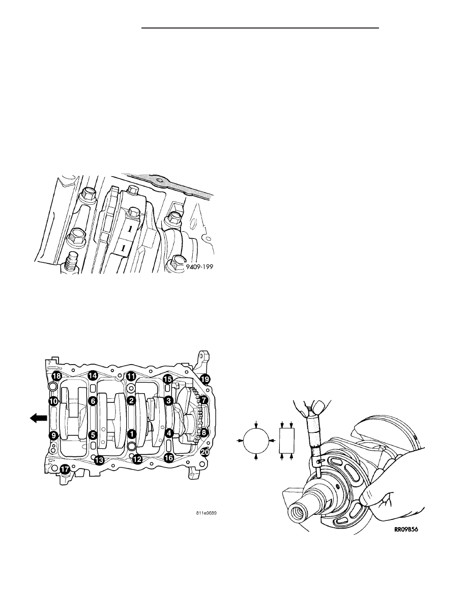
(19)
Remove all bed plate bolts from the engine
block (Fig. 56).
(20) Using a mallet tap the bed plate loose from
the engine block dowel pins.
CAUTION: Do not pry up on one side of the bed
plate. Damage may occur to cylinder block to bed
plate alignment and thrust bearing.
(21) Bedplate should be removed evenly from the
cylinder block dowel pins to prevent damage to the
dowel pins and thrust bearing.
CAUTION: Use extreme care when handling crank-
shaft. Tone wheel damage can occur if crankshaft is
mis-handled.
(22) Lift out crankshaft from cylinder block. Do
not damage the main bearings or journals when
removing the crankshaft.
(23) Remove the target ring mounting screws and
discard.
(24) Remove the target ring from the crankshaft.
INSPECTION
The crankshaft journals should be checked for
excessive wear, taper and scoring (Fig. 57). Limits of
taper or out of round on any crankshaft journals
should be held to 0.025 mm (0.001 in.). Journal
grinding should not exceed 0.305 mm (0.012 in.)
under the standard journal diameter. DO NOT grind
thrust faces of No. 3 main bearing. DO NOT nick
crank pin or bearing fillets. After grinding, remove
rough edges from crankshaft oil holes and clean out
all passages.
CAUTION: With the nodular cast iron crankshafts, it
is important that the final paper or cloth polish be
in the same direction as normal rotation in the
engine.
Fig. 55 Identify Connecting Rod to Cylinder -
Typical
Fig. 56 Main Bearing Caps/Bed Plate Bolt Removal
Sequence
Fig. 57 Crankshaft Journal Measurements - Typical
9 - 46
ENGINE 2.0L SOHC
PL/SRT-4
CRANKSHAFT (Continued)