Dodge Neon / Neon SRT-4. Manual - part 237


  Index      Dodge     Dodge Neon / Neon SRT-4 - service repair manual 2005 year


Search            


Content   ..  235  236  237  238   ..


Dodge Neon / Neon SRT-4. Manual - part 237


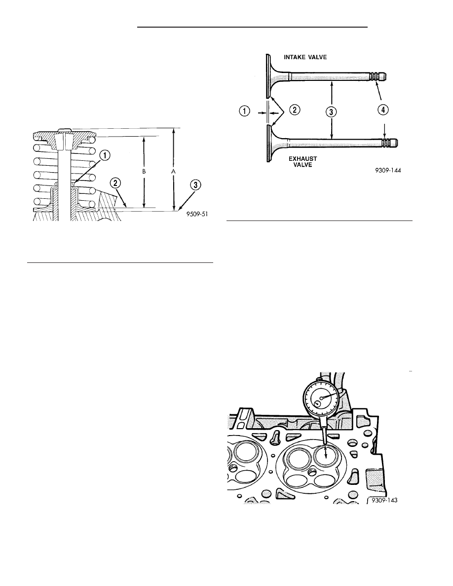
(9) Check valve tip to spring seat dimensions A

after machining the valve seats or faces. Grind valve
tip until within specifications. Measure from valve
tip to spring seat when installed in the head (mea-
surement A) (Fig. 46). For valve tip specifications,
(Refer to 9 - ENGINE - SPECIFICATIONS). The
valve tip chamfer is needed to be reground to prevent
seal damage when the valve is installed.

REMOVAL

(1) Remove valve spring. (Refer to 9 - ENGINE/

CYLINDER HEAD/VALVE SPRINGS - REMOVAL)

(2) Before removing valve, remove any burrs

from valve stem lock grooves to prevent dam-
age to the valve guides. 
Identify valves to insure
installation in original location.

(3) Remove valve(s) from cylinder head.

CLEANING

(1) Clean

all

valves

thoroughly

and

discard

burned, warped and cracked valves.

INSPECTION

VALVES

(1) Measure valve stems for wear (Fig. 47) approx-

imately 60 mm (2.36 in.) below the valve lock
grooves. For valve specifications (Refer to 9 -
ENGINE - SPECIFICATIONS).

NOTE: Valve stems are chrome plated and should
not be polished (Fig. 47).

VALVE GUIDES

NOTE: Replace cylinder head if stem-to-guide clear-
ance exceeds specifications, or if guide is loose in
cylinder head.

(1) Measure valve stem-to-guide clearance as fol-

lows:

(2) Install valve into cylinder head so it is 15 mm

(0.590 in.) off the valve seat. A small piece of hose
may be used to hold valve in place.

(3) Attach dial indicator Tool C-3339 to cylinder

head and set it at right angle of valve stem being
measured (Fig. 48).

(4) Move valve to and from the indicator. (Refer to

9 - ENGINE - SPECIFICATIONS)

Fig. 46 Spring Installed

1 - GARTER SPRING
2 - VALVE SPRING SEAT
3 - CYLINDER HEAD SURFACE

Fig. 47 Intake and Exhaust Valves

1 - MARGIN
2 - FACE
3 - STEM
4 - VALVE SPRING RETAINER LOCK GROOVES

Fig. 48 Measuring Valve Guide

9 - 42

ENGINE 2.0L SOHC

PL/SRT-4

INTAKE/EXHAUST VALVES & SEATS (Continued)

(5) Check valve guide height (Fig. 49).

INSTALLATION

(1) Coat valve stems with clean engine oil.
(2) Install valve in cylinder head.
(3) Install valve seal. (Refer to 9 - ENGINE/CYL-

INDER HEAD/VALVE STEM SEALS - INSTALLA-
TION)

(4) Install valve springs. (Refer to 9 - ENGINE/

CYLINDER HEAD/VALVE SPRINGS - INSTALLA-
TION)

ENGINE BLOCK

DESCRIPTION

The cast iron cylinder block is a two-piece assem-

bly, consisting of the cylinder block and bed plate
(Fig. 50). The bed plate incorporates the main bear-
ing caps and bolts to the cylinder block. This design
offers a much stronger lower end and increased cyl-
inder block rigidity. The rear oil seal retainer is inte-
gral with the block. The bed plate and block are
serviced as an assembly.

STANDARD PROCEDURE

CYLINDER BORE HONING

(1) Used carefully, the cylinder bore resizing hone,

recommended tool C-823 or equivalent, equipped
with 220 grit stones, is the best tool for this honing
procedure. In addition to deglazing, it will reduce
taper and out-of-round as well as removing light
scuffing, scoring or scratches. Usually a few strokes
will clean up a bore and maintain the required lim-
its.

(2) Deglazing of the cylinder walls may be done

using a cylinder surfacing hone, recommended tool
C-3501 or equivalent, equipped with 280 grit stones,
if the cylinder bore is straight and round. 20–60
strokes depending on the bore condition, will be suf-
ficient to provide a satisfactory surface. Use a light
honing oil. Do not use engine or transmission oil,
mineral spirits or kerosene. 
Inspect cylinder walls
after each 20 strokes.

(3) Honing should be done by moving the hone up

and down fast enough to get a cross-hatch pattern.
When hone marks intersect at 40-60 degrees, the
cross hatch angle is most satisfactory for proper seat-
ing of rings (Fig. 51).

Fig. 49 Valve Guide Height

1 - VALVE GUIDE
2 - 13.25 - 13.75 MM (0.521 - 0.541 IN.)
3 - SPRING SEAT

Fig. 50 Cylinder Block and Bed plate

1 - CYLINDER BLOCK
2 - BED PLATE

Fig. 51 Cylinder Bore Cross-Hatch Pattern

1 - CROSS-HATCH PATTERN
2 - 40°–60°

PL/SRT-4

ENGINE 2.0L SOHC

9 - 43

INTAKE/EXHAUST VALVES & SEATS (Continued)

(4)

A controlled

hone

motor

speed

between

200–300 RPM is necessary to obtain the proper cross-
hatch angle. The number of up and down strokes per
minute can be regulated to get the desired 40–60
degree angle. Faster up and down strokes increase
the cross-hatch angle.

(5) After honing, it is necessary that the block be

cleaned again to remove all traces of abrasive.

CAUTION: Ensure all abrasives are removed from
engine parts after honing. It is recommended that a
solution of soap and hot water be used with a
brush and the parts then thoroughly dried. The bore
can be considered clean when it can be wiped
clean with a white cloth and cloth remains clean.
Oil the bores after cleaning to prevent rusting.

CLEANING

Clean cylinder block thoroughly using a suitable

cleaning solvent.

INSPECTION

ENGINE BLOCK

(1) Clean cylinder block thoroughly and check all

core hole plugs for evidence of leaking.

(2) If new core plugs are to be installed, (Refer to 9

- ENGINE - STANDARD PROCEDURE - ENGINE
CORE AND OIL GALLERY PLUGS).

(3) Examine block and cylinder bores for cracks or

fractures.

(4) Check block deck surfaces for flatness. Deck

surface must be within service limit of 0.1 mm (0.004
in.).

CYLINDER BORE

NOTE: The cylinder bores should be measured at
normal room temperature, 21°C (70°F).

The cylinder walls should be checked for out-of-

round and taper with Tool C119 or equivalent (Fig.
52) (Refer to 9 - ENGINE - SPECIFICATIONS). If
the cylinder walls are badly scuffed or scored, the
cylinder block should be replaced, and new pistons
and rings fitted.

Measure the cylinder bore at three levels in direc-

tions A and B (Fig. 52). Top measurement should be
10 mm (3/8 in.) down and bottom measurement
should be 10 mm (3/8 in.) up from bottom of bore.
(Refer to 9 - ENGINE - SPECIFICATIONS).

CRANKSHAFT

STANDARD PROCEDURE - CRANKSHAFT END
PLAY

(1) Mount a dial indicator to front of engine, locat-

ing probe on nose of the crankshaft (Fig. 53).

(2) Move crankshaft all the way to the rear of its

travel.

(3) Zero the dial indicator.
(4) Move crankshaft all the way to the front of its

travel and read the dial indicator. For crankshaft
specifications (Refer to 9 - ENGINE - SPECIFICA-
TIONS)

Fig. 52 Checking Cylinder Bore Size

Fig. 53 Checking Crankshaft End Play - Typical

9 - 44

ENGINE 2.0L SOHC

PL/SRT-4

ENGINE BLOCK (Continued)

REMOVAL - CRANKSHAFT

(1) Remove engine assembly from vehicle (Refer to

9 - ENGINE - REMOVAL).

(2) Separate transaxle from engine.
(3) Remove drive plate/flexplate.
(4) Remove crankshaft rear oil seal (Refer to 9 -

ENGINE/ENGINE

BLOCK/CRANKSHAFT

OIL

SEAL - REAR - REMOVAL).

(5) Mount engine on a suitable repair stand.
(6) Drain engine oil.
(7) Remove crankshaft vibration damper (Refer to

9

-

ENGINE/ENGINE

BLOCK/VIBRATION

DAMPER - REMOVAL).

(8) Remove front timing belt cover, front engine

mount bracket, and timing belt (Refer to 9 -
ENGINE/VALVE

TIMING/TIMING

BELT

AND

SPROCKETS - REMOVAL).

(9) Remove the timing belt tensioner and pulley

bracket (Refer to 9 - ENGINE/VALVE TIMING/TIM-
ING BELT TENSIONER & PULLEY - REMOVAL).

(10) Remove camshaft sprocket and rear timing

belt cover (Refer to 9 - ENGINE/VALVE TIMING/
TIMING BELT COVER(S) - REMOVAL).

(11) Remove crankshaft sprocket (Refer to 9 -

ENGINE/ENGINE

BLOCK/CRANKSHAFT

OIL

SEAL - FRONT - REMOVAL).

(12) Remove oil filter and adapter (Fig. 54).
(13) Remove oil pan (Refer to 9 - ENGINE/LUBRI-

CATION/OIL PAN - REMOVAL).

(14) Remove oil pump pick-up tube.
(15) Remove oil pump (Refer to 9 - ENGINE/LU-

BRICATION/OIL PUMP - REMOVAL).

(16) Remove crankshaft position sensor (Fig. 54).

Fig. 54 Engine Block and Components

1 - OIL PASSAGE O-RING
2 - FRONT CRANKSHAFT SEAL
3 - UPPER BEARING (GROOVED)
4 - THRUST BEARINGS
5 - BOLT
6 - O-RING
7 - NIPPLE
8 - OIL FILTER ADAPTER

9 - BEDPLATE
10 - CRANKSHAFT POSITION SENSOR
11 - CONNECTING ROD BEARINGS
12 - PISTON AND CONNECTING ROD ASSEMBLY
13 - REAR CRANKSHAFT SEAL
14 - CRANKSHAFT
15 - ENGINE BLOCK

PL/SRT-4

ENGINE 2.0L SOHC

9 - 45

CRANKSHAFT (Continued)


Content   ..  235  236  237  238   ..