Dodge Neon / Neon SRT-4. Manual - part 99


  Index      Dodge     Dodge Neon / Neon SRT-4 - service repair manual 2005 year


Search            


Content   ..  97  98  99  100   ..


Dodge Neon / Neon SRT-4. Manual - part 99


REMOVAL

(1) Disconnect and isolate the battery negative

cable (Fig. 21).

(2) Remove both upper and lower steering column

shrouds. (Refer to 19 - STEERING/COLUMN/UPPER
SHROUD - REMOVAL).

(3) Disconnect both posi-lock harness connectors at

the rear of the multi-function switch (Fig. 22) and
(Fig. 23).

(4) Remove multi-function switch mounting screws

(Fig. 22) and (Fig. 23).

(5) The combination flasher must be transferred to

new multi-function switch if replacing (Fig. 22).

(6) The windshield wiper/washer switch must be

transferred to the new multi-function switch. (Refer
to 8 - ELECTRICAL/WIPERS/WASHERS/WIPER/
WASHER SWITCH - REMOVAL).

INSTALLATION

(1) The windshield wiper/washer switch must be

transferred to the new multi-function switch. (Refer
to 8 - ELECTRICAL/WIPERS/WASHERS/WIPER/
WASHER SWITCH - INSTALLATION).

(2) The combination flasher must be transferred to

new multi-function switch if replacing.

(3) Install the multi-function switch mounting

screws. Tighten multi-function switch to column
retaining screws to 3 N·m (27 in. lbs.) torque.

(4) Connect both posi-lock harness connectors at

the rear of the multi-function switch.

(5) Instal both upper and lower steering column

shrouds. (Refer to 19 - STEERING/COLUMN/UPPER
SHROUD - INSTALLATION).

(6) Connect the battery negative cable.

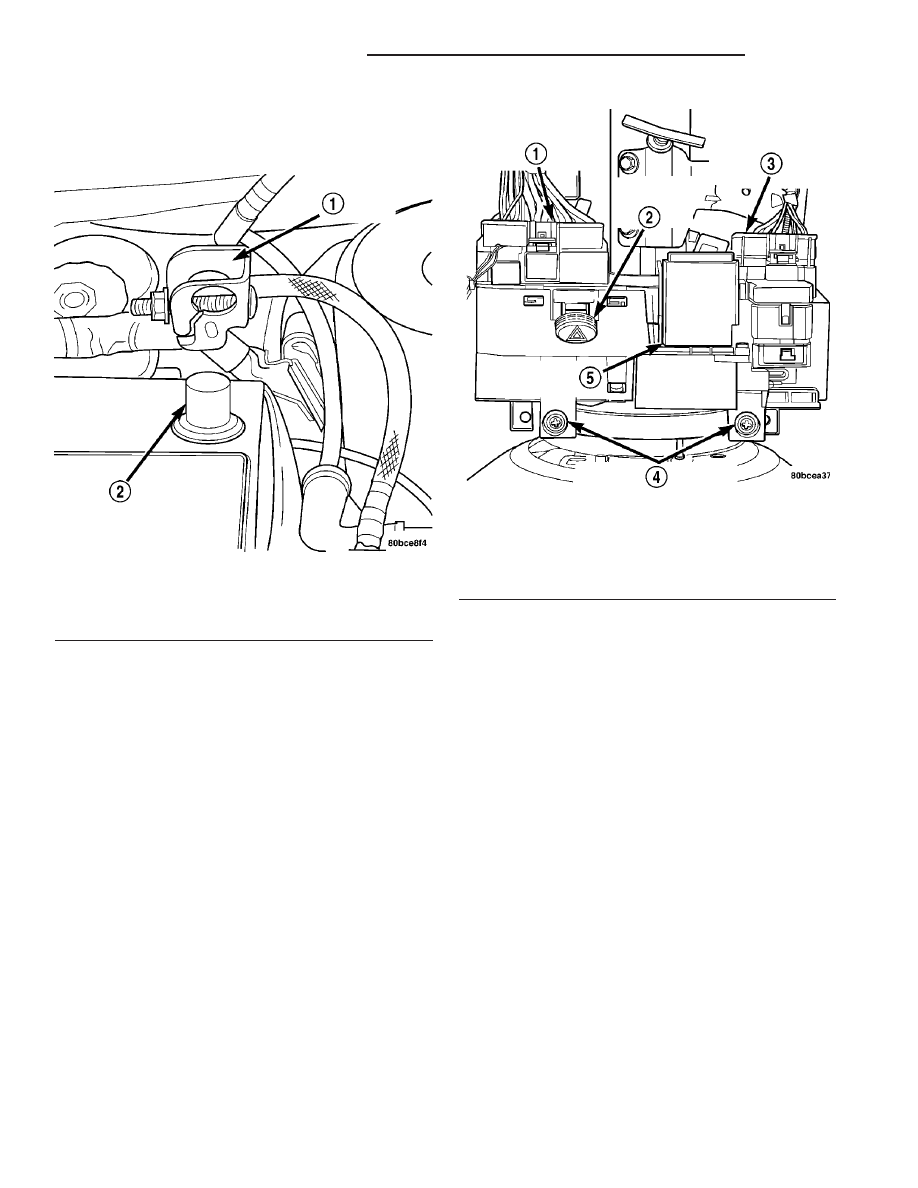
Fig. 21 DISCONNECT AND ISOLATE BATTERY

NEGATIVE CABLE

1 - NEGATIVE CABLE
2 - NEGATIVE BATTERY POST

Fig. 22 MULTI-FUNCTION SWITCH MOUNTING

1 - MULTI-FUNCTION SWITCH CONNECTOR
2 - HAZARD/WARNING SWITCH
3 - WINDSHIELD WIPER/WASHER SWITCH CONNECTOR
4 - MOUNTING SCREWS
5 - COMBINATION FLASHER

8L - 24

LAMPS/LIGHTING - EXTERIOR

PL/SRT-4

MULTI-FUNCTION SWITCH (Continued)

Fig. 23 MULTI-FUNCTION SWITCH - REMOVE/INSTALL

1 - MULTI-FUNCTION SWITCH CONNECTORS

3 - MULTI-FUNCTION SWITCH

2 - RETAINING SCREWS

PL/SRT-4

LAMPS/LIGHTING - EXTERIOR

8L - 25

MULTI-FUNCTION SWITCH (Continued)

REAR FOG LAMP

DESCRIPTION

Therear fog lamps can be found in the rear of the

vehicle, integrated into the rear tail lamp assembly.
Rear fog lamps utilize a red lens and clear bulb.

OPERATION

The rear fog lamps are turned ON and OFF with

the rear fog lamp switch. (Refer to 8 - ELECTRICAL/
LAMPS/LIGHTING

-

EXTERIOR/FOG

LAMP

SWITCH - OPERATION). Refer to Wiring Diagrams
for a complete system schematic.

DIAGNOSIS AND TESTING - REAR FOG LAMP
- EXPORT

Refer to Wiring Diagrams for a complete system

schematic.

(1) Remove the rear fog lamp bulb and check for

burned out condition. Replace bulb if necessary.

(2) If bulb appears OK, reinstall the bulb in its

socket and rotate the ignition switch to the “ON”
position. Turn the rear fog lamp “ON” and check for
lamp operation. If lamp is still inoperative proceed to
Step 3

(3) Remove lamp bulb and check for proper power

(12v) and ground connections in lamp socket. If
power and/or ground connections are not present,
trace wire until open or short is found. Refer to Wir-
ing Diagrams for a complete system schematic.

REMOVAL

REAR FOG LAMP UNIT

(1) Disconnect and isolate the battery negative

cable.

(2) Remove the appropriate two rear fog lamp

retaining screws.

(3) Pull the fog lamp assembly from the rear

bumper fascia.

(4) Rotate and pull the lamp socket from the lamp

housing.

(5) Remove lamp assembly from vehicle.

REAR FOG LAMP BULB

(1) Remove the fog lamp unit from the rear

bumper fascia (Refer to 8 - ELECTRICAL/LAMPS/
LIGHTING - EXTERIOR/FOG LAMP - REMOVAL).

(2) Pull bulb out of socket and replace bulb (Fig.

24).

INSTALLATION

REAR FOG LAMP UNIT

(1) Install the lamp socket into the lamp housing.
(2) Install the lamp assembly into rear bumper

fascia.

(3) Install the appropriate two rear fog lamp

retaining screws.

(4) Connect the battery negative cable.

REAR FOG LAMP BULB

(1) Push in bulb (Fig. 24).
(2) Install the fog lamp unit into the rear bumper

fascia (Refer to 8 - ELECTRICAL/LAMPS/LIGHT-
ING - EXTERIOR/FOG LAMP - INSTALLATION).

Fig. 24 REAR FOG LAMP SOCKET

1 - REAR FOG LAMP
2 - REAR FOG LAMP SOCKET

8L - 26

LAMPS/LIGHTING - EXTERIOR

PL/SRT-4

TAIL LAMP

REMOVAL

(1) Disconnect and isolate the battery negative

cable.

(2) Move trunk lining as necessary from rear clo-

sure panel to gain access to back of tail lamp.

(3) Remove bulb socket from tail lamp through

openings in rear closure panel (Fig. 25).

(4) Pull bulb from socket.

INSTALLATION

(1) Push bulb into socket.
(2) Install bulb socket into tail lamp through open-

ings in rear closure panel.

(3) Reposition trunk lining to rear closure panel.
(4) Connect the battery negative cable.

TAIL LAMP UNIT

REMOVAL

(1) Disconnect and isolate the battery negative

cable.

(2) Move trunk lining as necessary from rear clo-

sure panel to gain access to back of tail lamp.

(3) Remove nuts attaching tail lamp to the rear

closure panel.

(4) Disconnect the wiring connectors from the bulb

sockets.

(5) Remove lamp housing from vehicle.

INSTALLATION

(1) Pull wiring and connectors through opening in

rear closure panel and install wiring connectors into
bulb sockets.

(2) Place lamp assembly into position.
(3) Install lamp assembly nuts.
(4) Reposition trunk lining.
(5) Connect the battery negative cable.
(6) Verify vehicle and system operation.

TRUNK LAMP UNIT

REMOVAL

(1) Disconnect and isolate the battery negative

cable.

(2) Insert a trim stick or small flat blade between

the lamp lens and rear shelf reinforcement panel.

(3) Pry the lamp lens downward.
(4) Disconnect wire connector.
(5) Remove lamp from vehicle.

INSTALLATION

(1) Place lamp into position.
(2) Connect wire connector.
(3) Install lamp lens.
(4) Connect battery negative cable.

Fig. 25 TAIL AND STOP LAMP BULB

1 - REAR CLOSURE PANEL
2 - TAIL LAMP
3 - SOCKET
4 - BULB

PL/SRT-4

LAMPS/LIGHTING - EXTERIOR

8L - 27


Content   ..  97  98  99  100   ..