Dodge Neon / Neon SRT-4. Manual - part 90
(4) Loosen screw attaching target magnet to rear
of camshaft (Fig. 10).
INSTALLATION
INSTALLATION - 1.6L
(1) Install sensor to cylinder head (Fig. 8).
(2) Tighten screws to 9 N·m (80 in. lbs.).
(3) Connect the electrical connector to the sensor
(Fig. 7).
(4) Relocate and install the 2 bolts to the power-
steering reservoir.
(5) Relocate the fuel line and radiator over flow
hose (Fig. 6).
(6) Connect the negative battery cable
INSTALLATION - 2.0L
The camshaft position sensor is mounted to the
rear of the cylinder head (Fig. 9).
The target magnet has two locating dowels that fit
into machined locating holes in end of the camshaft.
(1) Install target magnet in end of camshaft.
Tighten mounting screw to 3.4 N·m (30 in. lbs.)
torque. Over torquing could cause cracks in magnet.
If magnet cracks replace it.
(2) Install camshaft position sensor. Tighten sensor
mounting screws to 9 N·m (80 in. lbs.) torque.
(3) Place brake booster hose and electrical harness
in holders on end of valve cover.
(4) Attach electrical connectors to camshaft posi-
tion sensor.
IGNITION COIL
DESCRIPTION
The coil pack consists of 2 coils molded together.
The coil pack is mounted on the valve cover (Fig. 11).
OPERATION
WARNING: THE DIRECT IGNITION SYSTEM GENER-
ATES APPROXIMATELY 40,000 VOLTS. PERSONAL
INJURY COULD RESULT FROM CONTACT WITH
THIS SYSTEM.
High tension leads route to each cylinder from the
coil. The coil fires two spark plugs every power
stroke. One plug is the cylinder under compression,
the other cylinder fires on the exhaust stroke. Coil
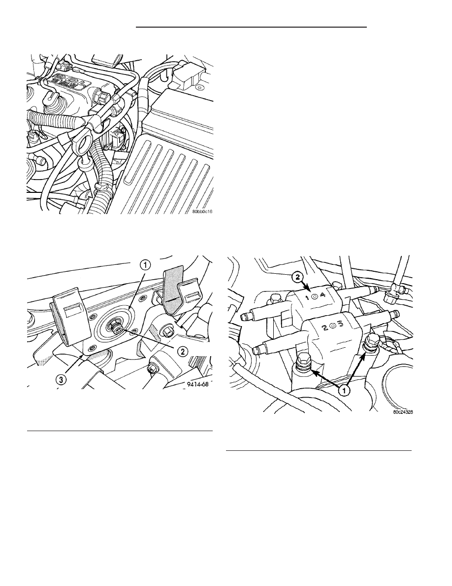
Fig. 9 Camshaft Position Sensor Location
Fig. 10 Target Magnet Removal/Installation
1 - TARGET MAGNET
2 - MOUNTING BOLT
3 - REAR OF CYLINDER HEAD
Fig. 11 Ignition Coil Pack
1 - RUBBER INSULATORS
2 - COIL
8I - 6
IGNITION CONTROL
PL/SRT-4
CAMSHAFT POSITION SENSOR (Continued)