Dodge Neon / Neon SRT-4. Manual - part 89


  Index      Dodge     Dodge Neon / Neon SRT-4 - service repair manual 2005 year


Search            


Content   ..  87  88  89  90   ..


Dodge Neon / Neon SRT-4. Manual - part 89


SPECIFICATIONS

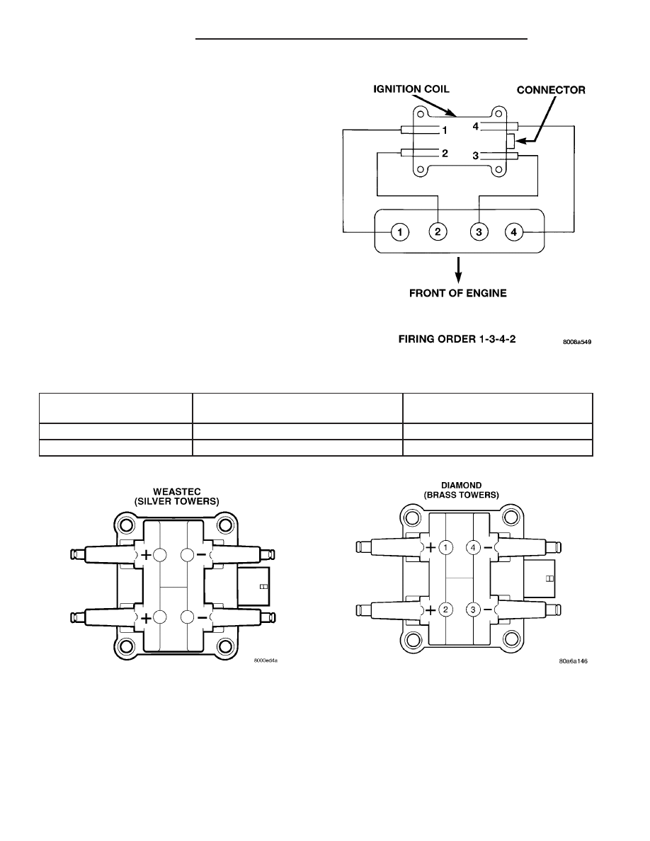
FIRING ORDER - 2.0/2.4/2.4 TURBO

IGNITION COIL

Coil Manufacture

Primary Resistance at 21°C-27°C
(70°F-80°F)

Secondary Resistance at 21°C-27°C
(70°F-80°F)

Weastec (Steel Towers)

0.45 to 0.65 Ohms

11,500 to 13,500 Ohms

Diamond (Brass Towers)

0.53 to 0.65 Ohms

10,900 to 14,700 Ohms

Coil Polarity

Coil Polarity

8I - 2

IGNITION CONTROL

PL/SRT-4

IGNITION CONTROL (Continued)

SPARK PLUG CABLE RESISTANCE

1.6L

CABLE

RESISTANCE

#1

2746 ohms— 8533 ohms

#2

2532 ohms— 7352 ohms

#3

3386 ohms— 10,453 ohms

#4

3632 ohms— 11,191 ohms

2.0/2.4L

CABLE

RESISTANCE

#1, #2, #3, #4

2280 ohms— 7290 ohms

2.4L TURBO

CABLE

RESISTANCE

#1,#2, #3

2280 ohms— 7290 ohms

#4

2686 ohms— 8062 ohms

SPECIAL TOOLS - EXPORT

AUTOMATIC SHUT DOWN
RELAY

DESCRIPTION

The ASD relay is located in the PDC (Fig. 1). The

inside top of the PDC cover has label showing relay
and fuse identification.

OPERATION

The Automatic Shutdown (ASD) relay supplies bat-

tery voltage to the fuel injectors, electronic ignition
coil and the heating elements in the oxygen sensors.

A buss bar in the Power Distribution Center (PDC)

supplies voltage to the solenoid side and contact side
of the relay. The fuse also protects the power circuit
for the fuel pump relay and pump. The fuse is
located in the PDC. Refer to the Wiring Diagrams for
circuit information.

The PCM controls the ASD relay by switching the

ground path for the solenoid side of the relay on and
off. The PCM turns the ground path off when the
ignition switch is in the Off position. When the igni-
tion switch is in On or Start, the PCM monitors the
crankshaft and camshaft position sensor signals to
determine engine speed and ignition timing (coil
dwell). If the PCM does not receive crankshaft and
camshaft position sensor signals when the ignition
switch is in the Run position, it will de-energize the
ASD relay.

PROTECTIVE SLEEVE

Fig. 1 Power Distribution Center (PDC)

PL/SRT-4

IGNITION CONTROL

8I - 3

IGNITION CONTROL (Continued)

REMOVAL

The relay is located in the Power Distribution Cen-

ter (PDC) (Fig. 2). The PDC is located next to the
battery in the engine compartment. For the location
of the relay within the PDC, refer to the PDC cover
for location. Check electrical terminals for corrosion
and repair as necessary.

CAMSHAFT POSITION
SENSOR

DESCRIPTION

On 2.0/2.4L engines the camshaft position sensor

attaches to the rear of the cylinder head. On 1.6L
engines it is mounted on the front side of the cylin-
der head. The PCM determines fuel injection syn-
chronization and cylinder identification from inputs
provided by the camshaft position sensor (Fig. 3) and
crankshaft position sensor. From the two inputs, the
PCM determines crankshaft position.

OPERATION

The PCM sends approximately 5 volts to the hall

affect sensor. This voltage is required to operate the
hall effect chip and the electronics inside the sensor.
A ground for the sensor is provided through the sen-
sor return circuit. The input to the PCM occurs on a
5 volt output reference circuit.

On 2.0/2.4L engines a target magnet attaches to

the rear of the camshaft and indexes to the correct
position. The target magnet has fourteen different
poles arranged in an asymmetrical pattern (Fig. 4).
As the target magnet rotates, the camshaft position
sensor senses the change in polarity (Fig. 5). The
sensor output switch switches from high (5.0 volts) to

low (0.5 volts) as the target magnet rotates. When
the north pole of the target magnet passes under the
sensor, the output switches high. The sensor output
switches low when the south pole of the target mag-
net passes underneath.

On 1.6L a raised platform on the cam sprocket

serves as a target. When the sensor detects the step,
the input voltage from the sensor to the PCM
switches from high (5 volts) to low (0.3 volts). As the
step returns away from the sensor, the input voltage
switches back to high (5 volts).

Fig. 2 Power Distribution Center (PDC)

Fig. 3 Camshaft

Fig. 4 Target Magnet—Typical

1 - CAM MAGNET/TARGET
2 - CAMSHAFT POSITION SENSOR

8I - 4

IGNITION CONTROL

PL/SRT-4

AUTOMATIC SHUT DOWN RELAY (Continued)

The sensor also acts as a thrust plate to control

camshaft endplay.

REMOVAL

REMOVAL - 1.6L

(1) Disconnect the negative battery cable.
(2) Relocate the fuel line and radiator over flow

hose (Fig. 6) and (Fig. 7).

(3) Disconnect the electrical connector from the

camshaft sensor.

(4) Remove the 2 bolts from the powersteering res-

ervoir and relocate.

(5) Remove 1 screws from sensor.
(6) Remove sensor (Fig. 8).

REMOVAL - 2.0L

The camshaft position sensor is mounted to the

rear of the cylinder head (Fig. 9).

(1) Remove brake booster hose and electrical con-

nector from holders on end of cylinder head cover
and reposition.

(2) Disconnect electrical connectors from camshaft

position sensor.

(3) Remove camshaft position sensor mounting

screws. Remove sensor.

Fig. 5 Target Magnet Polarity

1 - TARGET MAGNET

Fig. 6 CAMSHAFT POSITION SENSOR LOCATION

Fig. 7 CAMSHAFT ACCESS

Fig. 8 CAMSHAFT POSITION SENSOR

PL/SRT-4

IGNITION CONTROL

8I - 5

CAMSHAFT POSITION SENSOR (Continued)


Content   ..  87  88  89  90   ..