Dodge Caliber. Manual - part 958


  Index      Dodge     Dodge Caliber - service repair manual 2007 year


Search            


Content   ..  956  957  958  959   ..


Dodge Caliber. Manual - part 958


3.

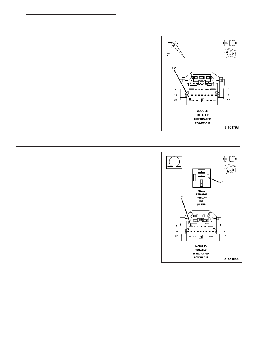
(N112) RADIATOR FAN CONTROL RELAY CONTROL CIRCUIT

Disconnect the TIPM C-11 harness connector.

Turn the ignition on, engine not running.

With a scan tool, select Radiator Cooling Fan Relay #1 Control State,
Toggle, to actuate the Radiator Fan Control Relay.

Using a 12–volt test light connected to battery voltage, probe the (N112)
Radiator Control Relay Control circuit in the TIPM C-11 harness con-
nector.

Does the test light illuminate and flash on and off?

Yes

>> Replace the Radiator Fan Control Relay.

Perform BODY VERIFICATION TEST – VER 1. (Refer to 8
-

ELECTRICAL/ELECTRONIC

CONTROL MODULES

-

STANDARD PROCEDURE)

No

>> Go To 4

4.

(N201) LOW/HIGH RADIATOR FAN CONTROL RELAY CONTROL CIRCUIT OPEN

Turn the ignition off.

Measure the resistance of the (N201) Low/High Radiator Fan Control
Relay Control circuit between the Rad Fan Control Relay #1 connector
and the TIPM C11 harness connector.

Is the resistance below 10.0 ohms?

Yes

>> Go To 5

No

>> Replace the PDM in accordance with the Service informa-

tion.

Perform BODY VERIFICATION TEST – VER 1. (Refer to 8
-

ELECTRICAL/ELECTRONIC

CONTROL MODULES

-

STANDARD PROCEDURE)

PM

ENGINE ELECTRICAL DIAGNOSTICS - DIESEL

9 - 1119

5.

(N201) LOW/HIGH RADIATOR FAN CONTROL RELAY CONTROL CIRCUIT SHORTED TO GROUND

Measure the resistance between ground and the (N201) Low/High Radi-
ator Fan Control Relay #1 Control circuit at the TIPM C11 harness con-
nection.

Is the resistance below 1000 ohms?

Yes

>> Replace the TIPM in accordance with the Service informa-

tion.

Perform BODY VERIFICATION TEST – VER 1. (Refer to 8
-

ELECTRICAL/ELECTRONIC

CONTROL MODULES

-

STANDARD PROCEDURE)

No

>> Replace Front Control Module in accordance with the Ser-

vice Information.

Perform BODY VERIFICATION TEST – VER 1. (Refer to 8
-

ELECTRICAL/ELECTRONIC

CONTROL MODULES

-

STANDARD PROCEDURE)

9 - 1120

ENGINE ELECTRICAL DIAGNOSTICS - DIESEL

PM

P0481-COOLING FAN 2 CONTROL CIRCUIT

For a complete wiring diagram Refer to Section 8W.

PM

ENGINE ELECTRICAL DIAGNOSTICS - DIESEL

9 - 1121

When Monitored:
With the ignition on. Battery voltage greater than 10 volts.

Set Condition:
The ECM receives a CAN Bus message from the TIPM indicating an open or shorted circuit on the Radiator
Fan Medium/High Relay Control circuit.

Possible Causes

FUSED B+ CIRCUITS

(N112) RADIATOR FAN RELAY CONTROL CIRCUIT OPEN

(N112) RADIATOR FAN RELAY CONTROL CIRCUIT SHORTED TO GROUND

RADIATOR FAN MEDIUM/HIGH RELAY

TOTALLY INTEGRATED POWER MODULE

Always perform the Pre-Diagnostic Troubleshooting procedure before proceeding. (Refer to 9 - ENGINE -
DIAGNOSIS AND TESTING).

Diagnostic Test

1.

RADIATOR FAN MEDIUM/HIGH RELAY OPERATION

Ignition on, engine not running.

With a scan tool, select Radiator Cooling Fan Relay #2 Control State, to actuate the Radiator Fan Medium/High
Relay.

Is the Cooling Fan Relay operating?

Yes

>> Refer to the *CHECKING FOR AN INTERMITTENT DTC Diagnostic Procedure. (Refer to 9 - ENGINE -

DIAGNOSIS AND TESTING)

Perform the ECM Verification Test Ver. 1. (Refer to 9 - ENGINE - DIAGNOSIS AND TESTING)

No

>> Go To 2

2.

FUSED B+ CIRCUITS

Turn the ignition off.

Remove the Radiator Medium/High Fan Relay.

Turn the ignition on.

Using a 12-volt test light connected to ground, probe the (A935) and
(A16) Fused B+ circuits in the Relay connection.

Does the test light illuminate brightly?

Yes

>> Go To 4

No

>> Go To 3

9 - 1122

ENGINE ELECTRICAL DIAGNOSTICS - DIESEL

PM


Content   ..  956  957  958  959   ..