Dodge Caliber. Manual - part 959
3.
RADIATOR FAN LOW/HIGH CONTROL RELAY SHORTED INTERNALLY
With the test light still at the Fused B+ circuits (Radiator Medium/High Fan Relay), remove the Radiator Fan Low/
High Control Relay.
When the relay is removed, does the test light illuminate brightly?
Yes
>> Replace the Radiator Fan Low/High Control Relay.
Perform BODY VERIFICATION TEST – VER 1. (Refer to 8 - ELECTRICAL/ELECTRONIC CONTROL
MODULES - STANDARD PROCEDURE)
No
>> Repair the open or short to ground in the Fused B+ circuits. Inspect the related fuse and repair as
necessary.
Perform BODY VERIFICATION TEST – VER 1. (Refer to 8 - ELECTRICAL/ELECTRONIC CONTROL
MODULES - STANDARD PROCEDURE)
4.
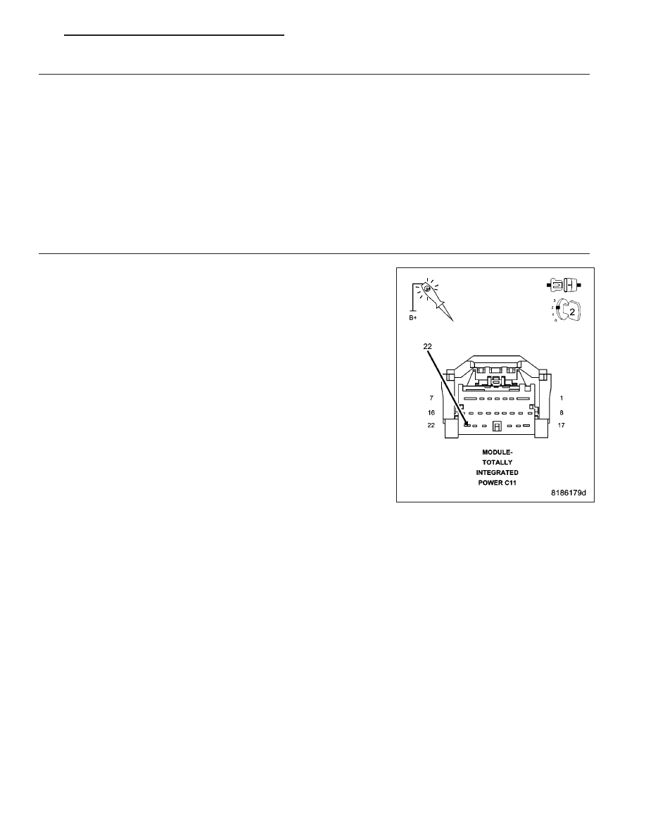
(N112) RADIATOR FAN RELAY CONTROL CIRCUIT
Disconnect the TIPM C-11 harness connector.
Turn the ignition on, engine not running.
With a scan tool, select Radiator Cooling Fan Relay #2 Control State
and then Toggle, to actuate the Radiator Fan Medium/High Relay.
Using a 12–volt test light connected to battery voltage, probe the (N112)
Radiator Fan High Relay Control circuit in the TIPM C-11 harness con-
nector.
Does the test light illuminate and flash on and off?
Yes
>> Replace the Radiator Fan Medium/High Relay.
Perform BODY VERIFICATION TEST – VER 1. (Refer to 8
-
ELECTRICAL/ELECTRONIC
CONTROL MODULES
-
STANDARD PROCEDURE)
No
>> Go To 5
PM
ENGINE ELECTRICAL DIAGNOSTICS - DIESEL
9 - 1123