Dodge Caliber. Manual - part 876


  Index      Dodge     Dodge Caliber - service repair manual 2007 year


Search            


Content   ..  874  875  876  877   ..


Dodge Caliber. Manual - part 876


6.

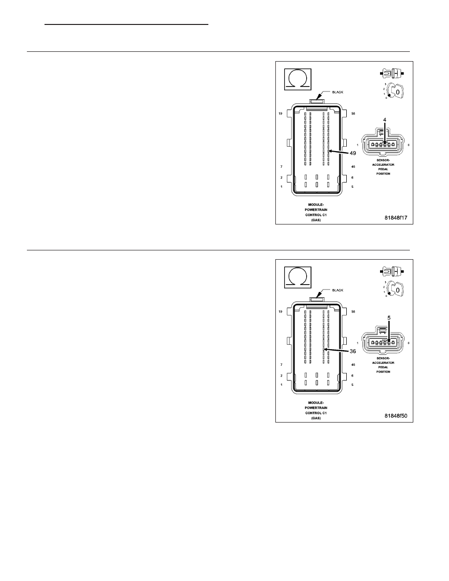
(K23) APP SIGNAL 1 CIRCUIT OPEN OR HIGH RESISTANCE

Turn the ignition off.

Measure the resistance of the (K23) APP Signal 1 between the Accel-
erator Pedal Position Sensor harness connector and the Powertrain
Control Module (PCM) harness connector.

Is the resistance below 5.0 ohms?

Yes

>> Go to 7

No

>> Repair the (K23) APP Signal 1 for an open circuit or high

resistance.

Perform the PCM Verification Test Ver. 1 (Refer to 9 -
ENGINE - DIAGNOSIS AND TESTING).

7.

(K167) SENSOR GROUND CIRCUIT OPEN OR HIGH RESISTANCE

Measure the resistance of the (K167) Sensor Ground circuit between
the Accelerator Pedal Position Sensor harness connector and the Pow-
ertrain Control Module (PCM) harness connector.

Is the resistance below 5.0 ohms?

Yes

>> Go to 8

No

>> Repair the (K167) Sensor Ground circuit for an open circuit

or high resistance.

Perform the PCM Verification Test Ver. 1 (Refer to 9 -
ENGINE - DIAGNOSIS AND TESTING).

PM

ENGINE ELECTRICAL DIAGNOSTICS - GPEC

9 - 791

8.

ACCELERATOR PEDAL POSITION SENSOR

Turn the ignition off.

Connect the Powertrain Control Module (PCM) connector.

Connect a jumper wire between the (K167) Sensor Ground circuit and
the (K23) APP Signal 1 circuit in the Accelerator Pedal Position Sensor
harness connector.

Turn the ignition on.

With the scan tool, read the Accelerator Pedal Position Sensor signal
voltage.

Is the voltage below 1.0 volt with the jumper wire in place?

Yes

>> Replace the Accelerator Pedal Position Sensor in accor-

dance with the Service Information.

Perform the PCM Verification Test Ver. 1 (Refer to 9 -
ENGINE - DIAGNOSIS AND TESTING).

No

>> Go to 9

9.

POWERTRAIN CONTROL MODULE (PCM)

Using the wiring diagram/schematic as a guide, inspect the wiring and connectors between the Accelerator Pedal
Position Sensor and the Powertrain Control Module (PCM).

Look for any chafed, pierced, pinched, or partially broken wires.

Look for broken, bent, pushed out or corroded terminals.

Monitor the scan tool data relative to this circuit and wiggle test the wiring and connectors.

Look for the data to change or for the DTC to reset during the wiggle test.

Refer to any Technical Service Bulletins that may apply.

Were any problems found?

Yes

>> Repair as necessary.

Perform the PCM Verification Test Ver. 1 (Refer to 9 - ENGINE - DIAGNOSIS AND TESTING).

No

>> Replace and program the Powertrain Control Module (PCM) in accordance with the Service Information.

Perform the PCM Verification Test Ver. 1 (Refer to 9 - ENGINE - DIAGNOSIS AND TESTING).

9 - 792

ENGINE ELECTRICAL DIAGNOSTICS - GPEC

PM

P2127-ACCELERATOR PEDAL POSITION SENSOR 2 CIRCUIT LOW

For a complete wiring diagram Refer to Section 8W

PM

ENGINE ELECTRICAL DIAGNOSTICS - GPEC

9 - 793

When Monitored:
With the ignition on and battery voltage greater than 10.4 volts.

Set Condition:
The PCM detects that the (K29) APP Signal 2 circuit is shorted low.

Possible Causes

INTERMITTENT DTC

(K858) 5 VOLT SUPPLY CIRCUIT SHORTED TO GROUND

(K29) APP SIGNAL 2 CIRCUIT SHORTED TO GROUND

(K858) 5 VOLT SUPPLY CIRCUIT SHORTED TO (K400) SENSOR GROUND CIRCUIT

(K858) 5 VOLT SUPPLY CIRCUIT SHORTED TO (K167) SENSOR GROUND CIRCUIT

(K29) APP SIGNAL 2 CIRCUIT SHORTED TO (K400) SENSOR GROUND CIRCUIT

(K29) APP SIGNAL 2 CIRCUIT SHORTED TO (K167) SENSOR GROUND CIRCUIT

(K858) 5 VOLT SUPPLY CIRCUIT OPEN OR HIGH RESISTANCE

(K29) APP SIGNAL 2 CIRCUIT OPEN OR HIGH RESISTANCE

ACCELERATOR PEDAL POSITION SENSOR

POWERTRAIN CONTROL MODULE (PCM)

Always perform the Pre-Diagnostic Troubleshooting procedure before proceeding. (Refer to 9 - ENGINE -
DIAGNOSIS AND TESTING)

Diagnostic Test

1.

DTC IS ACTIVE

Ignition on, engine not running.

NOTE: Diagnose and repair any system voltage or sensor supply voltage DTCs before continuing with this
test.
With the scan tool, select View DTCs.

Is the status Active for this DTC?

Yes

>> Go to 2

No

>> Refer to the *CHECKING FOR AN INTERMITTENT DTC Diagnostic Procedure. (Refer to 9 - ENGINE -

DIAGNOSIS AND TESTING)

2.

(K858) 5 VOLT SUPPLY CIRCUIT VOLTAGE

Turn the ignition off.

Disconnect the Accelerator Pedal Position Sensor connector.

Turn the ignition on.

Measure the voltage of the (K858) 5 Volt Supply circuit in the Acceler-
ator Pedal Position Sensor harness connector.

Is the voltage above 4.5 volts?

Yes

>> Go to 6

No

>> Go to 3

9 - 794

ENGINE ELECTRICAL DIAGNOSTICS - GPEC

PM


Content   ..  874  875  876  877   ..