Dodge Caliber. Manual - part 874


  Index      Dodge     Dodge Caliber - service repair manual 2007 year


Search            


Content   ..  872  873  874  875   ..


Dodge Caliber. Manual - part 874


When Monitored:
With the ignition on and battery voltage greater than 10.4 volts.

Set Condition:
The PCM detects that the (K23) APP Signal 1 circuit is shorted low.

Possible Causes

INTERMITTENT DTC

(F856) 5 VOLT SUPPLY CIRCUIT SHORTED TO GROUND

(K23) APP SIGNAL 1 CIRCUIT SHORTED TO GROUND

(F856) 5 VOLT SUPPLY CIRCUIT SHORTED TO (K167) SENSOR GROUND CIRCUIT

(F856) 5 VOLT SUPPLY CIRCUIT SHORTED TO (K400) SENSOR GROUND CIRCUIT

(K23) APP SIGNAL 1 CIRCUIT SHORTED TO (K167) SENSOR GROUND CIRCUIT

(K23) APP SIGNAL 1 CIRCUIT SHORTED TO (K400) SENSOR GROUND CIRCUIT

(F856) 5 VOLT SUPPLY CIRCUIT OPEN OR HIGH RESISTANCE

(K23) APP SIGNAL 1 CIRCUIT OPEN OR HIGH RESISTANCE

ACCELERATOR PEDAL POSITION SENSOR

POWERTRAIN CONTROL MODULE (PCM)

Always perform the Pre-Diagnostic Troubleshooting procedure before proceeding. (Refer to 9 - ENGINE -
DIAGNOSIS AND TESTING)

Diagnostic Test

1.

DTC IS ACTIVE

Ignition on, engine not running.

NOTE: Diagnose and repair any system voltage or sensor supply voltage DTCs before continuing with this
test.
With the scan tool, select View DTCs.

Is the status Active for this DTC?

Yes

>> Go to 2

No

>> Refer to the *CHECKING FOR AN INTERMITTENT DTC Diagnostic Procedure. (Refer to 9 - ENGINE -

DIAGNOSIS AND TESTING)

2.

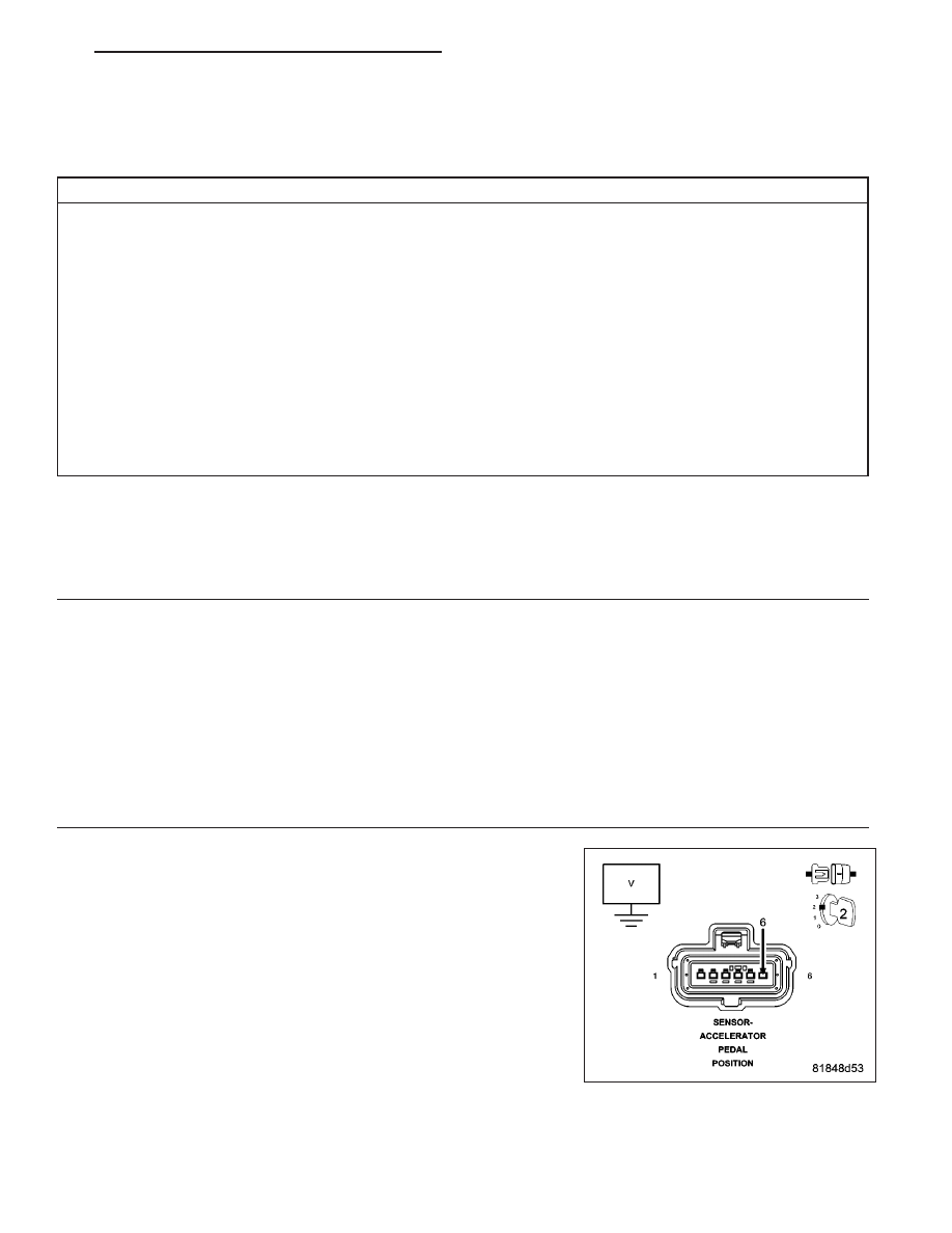
(F856) 5 VOLT SUPPLY CIRCUIT VOLTAGE

Turn the ignition off.

Disconnect the Accelerator Pedal Position Sensor connector.

Turn the ignition on.

Measure the voltage of the (F856) 5 Volt Supply circuit in the Acceler-
ator Pedal Position Sensor harness connector.

Is the voltage above 4.5 volts?

Yes

>> Go to 6

No

>> Go to 3

PM

ENGINE ELECTRICAL DIAGNOSTICS - GPEC

9 - 783

3.

(F856) 5 VOLT SUPPLY CIRCUIT SHORTED TO GROUND

Turn the ignition on.

Disconnect the Powertrain Control Module (PCM) connector.

Measure the resistance between ground and the (F856) 5 Volt Supply
circuit in the Accelerator Pedal Position Sensor harness connector.

Is the resistance above 1000 ohms?

Yes

>> Go to 4

No

>> Repair the (F856) 5 Volt Supply circuit for a short to ground.

Perform the PCM Verification Test Ver. 1 (Refer to 9 -
ENGINE - DIAGNOSIS AND TESTING).

4.

(F856) 5 VOLT SUPPLY CIRCUIT SHORTED TO (K167) SENSOR GROUND CIRCUIT

Measure the resistance between the (F856) 5 Volt Supply circuit and
the (K167) Sensor Ground circuit in the Accelerator Pedal Position Sen-
sor harness connector.

Is the resistance above 100 ohms?

Yes

>> Go to 5

No

>> Repair the (F856) 5 Volt Supply circuit for a short to the

(K167) Sensor Ground circuit.

Perform the PCM Verification Test Ver. 1 (Refer to 9 -
ENGINE - DIAGNOSIS AND TESTING).

5.

(F856) 5 VOLT SUPPLY CIRCUIT SHORTED TO (K400) SENSOR GROUND CIRCUIT

Measure the resistance between the (F856) 5 Volt Supply circuit and
the (K400) Sensor Ground circuit in the Accelerator Pedal Position Sen-
sor harness connector.

Is the resistance above 100 ohms?

Yes

>> Go to 6

No

>> Repair the (F856) 5 Volt Supply circuit for a short to the

(K400) Sensor Ground circuit.

Perform the PCM Verification Test Ver. 1 (Refer to 9 -
ENGINE - DIAGNOSIS AND TESTING).

9 - 784

ENGINE ELECTRICAL DIAGNOSTICS - GPEC

PM

6.

(F856) 5 VOLT SUPPLY CIRCUIT OPEN OR HIGH RESISTANCE

Measure the resistance of the (F856) 5 Volt Supply circuit between the
Accelerator Pedal Position Sensor harness connector and the Power-
train Control Module (PCM) harness connector.

Is the resistance below 5.0 ohms?

Yes

>> Go to 7

No

>> Repair the (F856) 5 Volt Supply circuit for an open circuit or

high resistance.

Perform the PCM Verification Test Ver. 1 (Refer to 9 -
ENGINE - DIAGNOSIS AND TESTING).

7.

(K23) APP SIGNAL 1 CIRCUIT SHORTED TO GROUND

Turn the ignition off.

Disconnect the Powertrain Control Module (PCM) connector.

Measure the resistance between ground and the (K23) APP Signal 1
circuit in the Accelerator Pedal Position Sensor harness connector.

Is the resistance above 100 ohms?

Yes

>> Go to 8

No

>> Repair the (K23) APP Signal 1 circuit for a short to ground.

Perform the PCM Verification Test Ver. 1 (Refer to 9 -
ENGINE - DIAGNOSIS AND TESTING).

8.

(K23) APP SIGNAL 1 CIRCUIT SHORTED TO (K167) SENSOR GROUND CIRCUIT

Measure the resistance between the (K23) APP Signal 1 circuit and the
(K167) Sensor Ground circuit in the Accelerator Pedal Position Sensor
harness connector.

Is the resistance above 100 ohms?

Yes

>> Go to 9

No

>> Repair the (K23) APP Signal 1 circuit for a short to the

(K167) Sensor Ground circuit.

Perform the PCM Verification Test Ver. 1 (Refer to 9 -
ENGINE - DIAGNOSIS AND TESTING).

PM

ENGINE ELECTRICAL DIAGNOSTICS - GPEC

9 - 785

9.

(K23) APP SIGNAL 1 CIRCUIT SHORTED TO (K400) SENSOR GROUND CIRCUIT

Measure the resistance between the (K23) APP Signal 1 circuit and the
(K400) Sensor Ground circuit in the Accelerator Pedal Position Sensor
harness connector.

Is the resistance above 100 ohms?

Yes

>> Go to 10

No

>> Repair the (K23) APP Signal 1 circuit for a short to the

(K400) Sensor Ground circuit.

Perform the PCM Verification Test Ver. 1 (Refer to 9 -
ENGINE - DIAGNOSIS AND TESTING).

10.

(K23) APP SIGNAL 1 CIRCUIT OPEN OR HIGH RESISTANCE

Measure the resistance of the (K23) APP Signal 1 circuit between the
Accelerator Pedal Position Sensor harness connector and the Power-
train Control Module (PCM) harness connector.

Is the resistance below 5.0 ohms?

Yes

>> Go to 11

No

>> Repair the (K23) APP Signal 1 circuit for an open circuit or

high resistance.

Perform the PCM Verification Test Ver. 1 (Refer to 9 -
ENGINE - DIAGNOSIS AND TESTING).

11.

ACCELERATOR PEDAL POSITION SENSOR

Turn the ignition off.

Connect the Powertrain Control Module (PCM) connector.

Connect a jumper wire between the (F856) 5 Volt Supply circuit and the
(K23) APP Signal 1 circuit in the Accelerator Pedal Position Sensor har-
ness connector.

Turn the ignition on.

With the scan tool, read the Accelerator Pedal Position Sensor signal
voltage.

Is the voltage above 4.5 volts with the jumper wire in place?

Yes

>> Replace the Accelerator Pedal Position Sensor in accor-

dance with the Service Information.

Perform the PCM Verification Test Ver. 1 (Refer to 9 -
ENGINE - DIAGNOSIS AND TESTING).

No

>> Go to 12

9 - 786

ENGINE ELECTRICAL DIAGNOSTICS - GPEC

PM


Content   ..  872  873  874  875   ..