Dodge Caliber. Manual - part 877


  Index      Dodge     Dodge Caliber - service repair manual 2007 year


Search            


Content   ..  875  876  877  878   ..


Dodge Caliber. Manual - part 877


3.

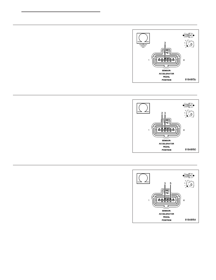
(K858) 5 VOLT SUPPLY CIRCUIT SHORTED TO GROUND

Turn the ignition on.

Disconnect the Powertrain Control Module (PCM) connector.

Measure the resistance between ground and the (K858) 5 Volt Supply
circuit in the Accelerator Pedal Position Sensor harness connector.

Is the resistance above 1000 ohms?

Yes

>> Go to 4

No

>> Repair the (K858) 5 Volt Supply circuit for a short to ground.

Perform the PCM Verification Test Ver. 1 (Refer to 9 -
ENGINE - DIAGNOSIS AND TESTING).

4.

(K858) 5 VOLT SUPPLY CIRCUIT SHORTED TO (K400) SENSOR GROUND CIRCUIT

Measure the resistance between the (K858) 5 Volt Supply circuit and
the (K400) Sensor Ground circuit in the Accelerator Pedal Position Sen-
sor harness connector.

Is the resistance above 100 ohms?

Yes

>> Go to 5

No

>> Repair the (K858) 5 Volt Supply circuit for a short to the

(K400) Sensor Ground circuit.

Perform the PCM Verification Test Ver. 1 (Refer to 9 -
ENGINE - DIAGNOSIS AND TESTING).

5.

(K858) 5 VOLT SUPPLY CIRCUIT SHORTED TO (K167) SENSOR GROUND CIRCUIT

Measure the resistance between the (K858) 5 Volt Supply circuit and
the (K167) Sensor Ground circuit in the Accelerator Pedal Position Sen-
sor harness connector.

Is the resistance above 100 ohms?

Yes

>> Go to 6

No

>> Repair the (K858) 5 Volt Supply circuit for a short to the

(K167) Sensor Ground circuit.

Perform the PCM Verification Test Ver. 1 (Refer to 9 -
ENGINE - DIAGNOSIS AND TESTING).

PM

ENGINE ELECTRICAL DIAGNOSTICS - GPEC

9 - 795

6.

(K858) 5 VOLT SUPPLY CIRCUIT OPEN OR HIGH RESISTANCE

Measure the resistance of the (K858) 5 Volt Supply circuit between the
Accelerator Pedal Position Sensor harness connector and the Power-
train Control Module (PCM) harness connector.

Is the resistance below 5.0 ohms?

Yes

>> Go to 7

No

>> Repair the (K858) 5 Volt Supply circuit for an open circuit or

high resistance.

Perform the PCM Verification Test Ver. 1 (Refer to 9 -
ENGINE - DIAGNOSIS AND TESTING).

7.

(K29) APP SIGNAL 2 CIRCUIT SHORTED TO GROUND

Turn the ignition off.

Disconnect the Powertrain Control Module (PCM) connector.

Measure the resistance between ground and the (K29) APP Signal 2
circuit in the Accelerator Pedal Position Sensor harness connector.

Is the resistance above 100 ohms?

Yes

>> Go to 8

No

>> Repair the (K29) APP Signal 2 circuit for a short to ground.

Perform the PCM Verification Test Ver. 1 (Refer to 9 -
ENGINE - DIAGNOSIS AND TESTING).

8.

(K29) APP SIGNAL 2 CIRCUIT SHORTED TO (K400) SENSOR GROUND CIRCUIT

Measure the resistance between the (K29) APP Signal 2 circuit and the
(K400) Sensor Ground circuit in the Accelerator Pedal Position Sensor
harness connector.

Is the resistance above 100 ohms?

Yes

>> Go to 9

No

>> Repair the (K29) APP Signal 2 circuit for a short to the

(K400) Sensor Ground circuit.

Perform the PCM Verification Test Ver. 1 (Refer to 9 -
ENGINE - DIAGNOSIS AND TESTING).

9 - 796

ENGINE ELECTRICAL DIAGNOSTICS - GPEC

PM

9.

(K29) APP SIGNAL 2 CIRCUIT SHORTED TO (K167) SENSOR GROUND CIRCUIT

Measure the resistance between the (K29) APP Signal 2 circuit and the
(K167) Sensor Ground circuit in the Accelerator Pedal Position Sensor
harness connector.

Is the resistance above 100 ohms?

Yes

>> Go to 10

No

>> Repair the (K29) APP Signal 2 circuit for a short to the

(K167) Sensor Ground circuit.

Perform the PCM Verification Test Ver. 1 (Refer to 9 -
ENGINE - DIAGNOSIS AND TESTING).

10.

(K29) APP SIGNAL 2 CIRCUIT OPEN OR HIGH RESISTANCE

Measure the resistance of the (K29) APP Signal 2 circuit between the
Accelerator Pedal Position Sensor harness connector and the Power-
train Control Module (PCM) harness connector.

Is the resistance below 5.0 ohms?

Yes

>> Go to 11

No

>> Repair the (K29) APP Signal 2 circuit for an open circuit or

high resistance.

Perform the PCM Verification Test Ver. 1 (Refer to 9 -
ENGINE - DIAGNOSIS AND TESTING).

11.

ACCELERATOR PEDAL POSITION SENSOR

Turn the ignition off.

Connect the Powertrain Control Module (PCM) connector.

Connect a jumper wire between the (K858) 5 Volt Supply circuit and the
(K29) APP Signal 2 circuit in the Accelerator Pedal Position Sensor har-
ness connector.

Turn the ignition on.

With the scan tool, read the Accelerator Pedal Position Sensor signal
voltage.

Is the voltage above 4.5 volts with the jumper wire in place?

Yes

>> Replace the Accelerator Pedal Position Sensor in accor-

dance with the Service Information.

Perform the PCM Verification Test Ver. 1 (Refer to 9 -
ENGINE - DIAGNOSIS AND TESTING).

No

>> Go to 12

PM

ENGINE ELECTRICAL DIAGNOSTICS - GPEC

9 - 797

12.

POWERTRAIN CONTROL MODULE (PCM)

Using the wiring diagram/schematic as a guide, inspect the wiring and connectors between the Accelerator Pedal
Position Sensor and the Powertrain Control Module (PCM).

Look for any chafed, pierced, pinched, or partially broken wires.

Look for broken, bent, pushed out or corroded terminals.

Monitor the scan tool data relative to this circuit and wiggle test the wiring and connectors.

Look for the data to change or for the DTC to reset during the wiggle test.

Refer to any Technical Service Bulletins that may apply.

Were any problems found?

Yes

>> Repair as necessary.

Perform the PCM Verification Test Ver. 1 (Refer to 9 - ENGINE - DIAGNOSIS AND TESTING).

No

>> Replace and program the Powertrain Control Module (PCM) in accordance with the Service Information.

Perform the PCM Verification Test Ver. 1 (Refer to 9 - ENGINE - DIAGNOSIS AND TESTING).

9 - 798

ENGINE ELECTRICAL DIAGNOSTICS - GPEC

PM


Content   ..  875  876  877  878   ..