Dodge Caliber. Manual - part 497
KNEE BLOCKER AIRBAG
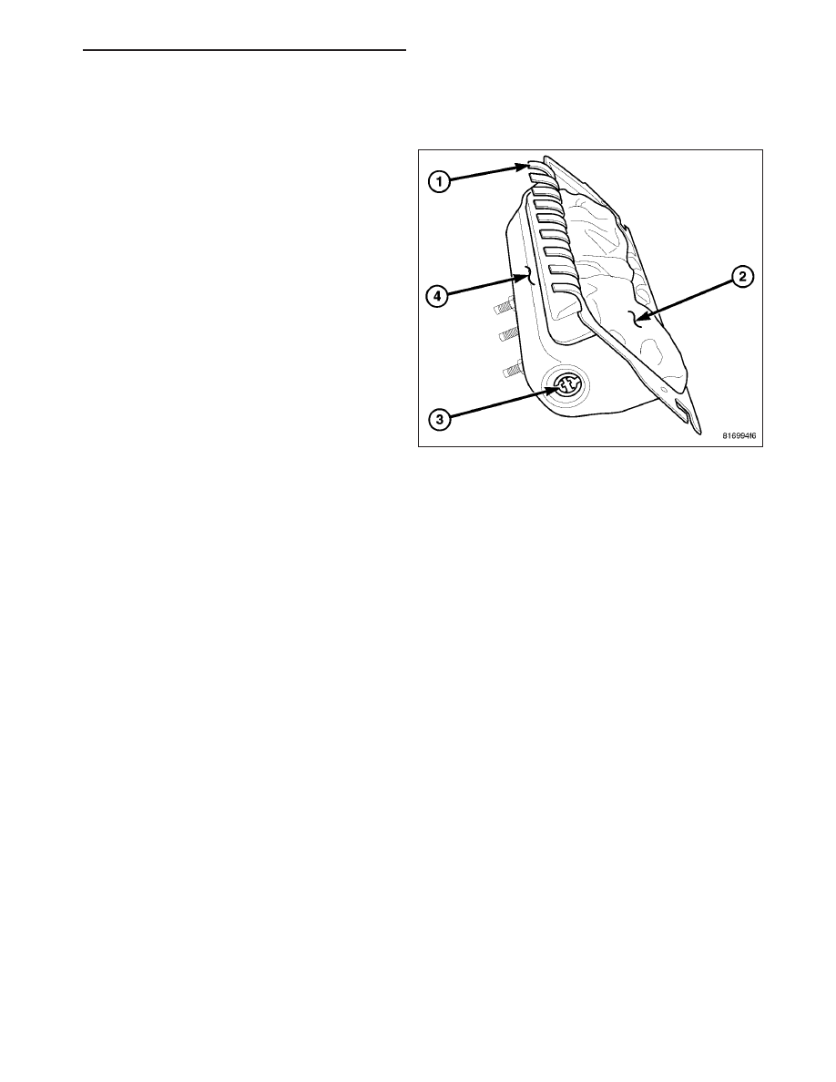
DESCRIPTION
The Knee Blocker Airbag is located on the driver side
of the vehicle below the steering column, at the bot-
tom edge of the instrument panel. The knee blocker
airbag contains:
•
A stamped steel housing (4) with retaining hooks
(1) for the knee blocker airbag trim cover to
attach to.
•
An airbag cushion (2)
•
An igniter (3)
WARNING:
Following
a
knee
blocker
airbag
deployment, the knee blocker airbag and instru-
ment panel assembly must be replaced. Refer to
the proper diagnostic information for diagnosis
and testing.
OPERATION
The knee blocker airbag is equipped with a single inflator. When the Occupant Restraint Controller (ORC) sends the
proper electrical signals to the initiator, the electrical energy generates enough heat to initiate a small pyrotechnic
charge which, in turn ignites chemical pellets within the inflator. Once ignited, these chemical pellets burn rapidly
and produce a large quantity of inert gas. The inflator is sealed to the back of the airbag housing and a diffuser in
the inflator directs all of the inert gas into the airbag cushion, causing the cushion to inflate. As the cushion inflates,
the knee blocker airbag trim deploy. Following an airbag deployment, the airbag cushion quickly deflates by venting
the inert gas towards the instrument panel through vent holes within the fabric used to construct the back panel of
the airbag cushion.
Some of the chemicals used to create the inert gas may be considered hazardous while in their solid state before
they are burned, but they are securely sealed within the airbag inflator. Typically, the potentially hazardous chemi-
cals are burned during an airbag deployment event.
WARNING: The inert gas that is produced when the chemicals are burned is harmless. However, a small
amount of residue from the burned chemicals may cause some temporary discomfort if it contacts the skin,
eyes, or breathing passages. If skin or eye irritation is noted, rinse the affected area with plenty of cool,
clean water. If breathing passages are irritated, move to another area where there is plenty of clean, fresh
air to breath. If the irritation is not alleviated by these actions, contact a physician.
PM
RESTRAINTS - SERVICE INFORMATION
8O - 385