Dodge Caliber. Manual - part 495


  Index      Dodge     Dodge Caliber - service repair manual 2007 year


Search            


Content   ..  493  494  495  496   ..


Dodge Caliber. Manual - part 495


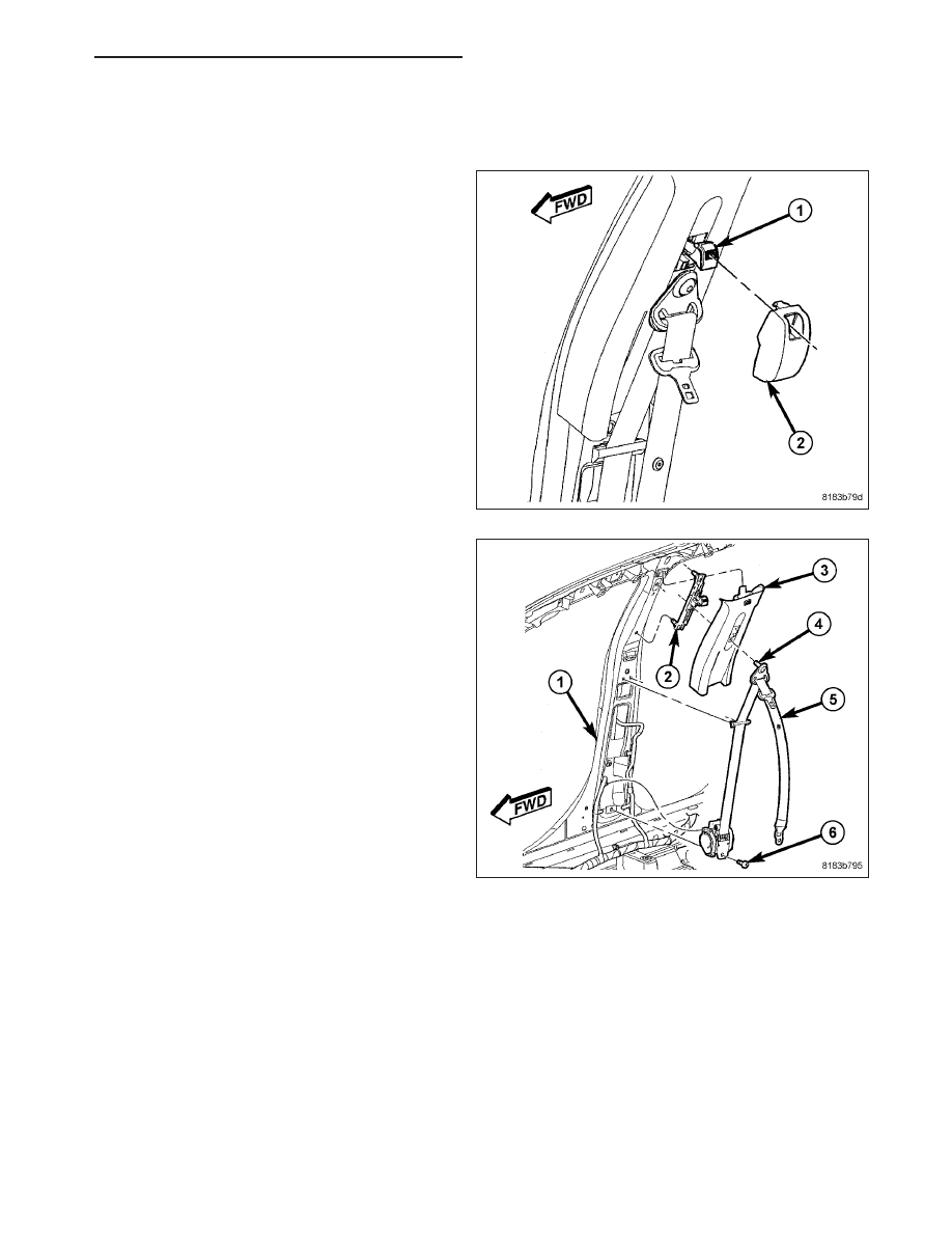
FRONT SEAT BELT HEIGHT ADJUSTER

REMOVAL

1. Firmly grasp the turning loop cover (2) and pull

inward to remove from height adjuster.

2. Remove the one bolt to the front seat belt retractor

turning loop (4).

3. Remove Upper B-pillar trim (Refer to 23 - BODY/

INTERIOR/B-PILLAR TRIM - REMOVAL).

PM

RESTRAINTS - SERVICE INFORMATION

8O - 377

4. Remove the two bolts (2) attaching front seat belt

height adjuster (3) to B-pillar (1).

5. Remove front seat belt height adjuster (3) from

vehicle.

INSTALLATION

1. Install front seat belt height adjuster (3) in vehicle.

2. Tighten the two bolts (2) attaching front seat belt

height adjuster (3) to B-pillar (1) to 40 N·m (29.5 ft.
lbs.).

8O - 378

RESTRAINTS - SERVICE INFORMATION

PM

3. Install the upper B-pillar trim (Refer to 23 - BODY/

INTERIOR/B-PILLAR TRIM - INSTALLATION).

4. Install the one bolt to the front seat belt retractor

turning loop (4). Tighten bolt to 40 N·m (29.5 ft.
lbs.).

5. Snap the turning loop cover (2) onto the height

adjuster.

PM

RESTRAINTS - SERVICE INFORMATION

8O - 379

IMPACT SENSOR

DESCRIPTION

FRONT

Two front impact sensors (1) are used on this vehicle,
one each for the left and right sides of the vehicle.
These sensors are mounted remotely from the impact
sensor that is internal to the Occupant Restraint Con-
troller (ORC). Each front sensor is secured with a
screw to the backs of the right and left vertical mem-
bers of the radiator support within the engine compart-
ment.

The right and left front impact sensors are identical in
construction and calibration. A cavity in the center of
the molded black plastic impact sensor housing con-
tains the electronic circuitry of the sensor which
includes an electronic communication chip and an
electronic impact sensor. Potting material that fills the
cavity to seal and protect the internal electronic cir-
cuitry and components. The front impact sensors are
each connected to the vehicle electrical system through the headlamp and dash wire harness.

The impact sensors cannot be repaired or adjusted and, if damaged or ineffective, they must be replaced.

SIDE

Four side impact sensors (1) are used on this vehicle
when it is equipped with the optional side airbags, two
each for the left and right sides of the vehicle. These
sensors are mounted remotely from the impact sensor
that is internal to the Occupant Restraint Controller
(ORC). Each side sensor is secured with a screw to
the right or left B-pillar and C-pillar.

The right and left side impact sensors are identical in construction and calibration. A cavity in the center of the
molded black plastic impact sensor housing contains the electronic circuitry of the sensor which includes an elec-
tronic communication chip and an electronic impact sensor. Potting material fills the cavity to seal and protect the
internal electronic circuitry and components. The side impact sensors are each connected to the vehicle electrical
system through the body wire harness.

The impact sensors cannot be repaired or adjusted and, if damaged or ineffective, they must be replaced.

8O - 380

RESTRAINTS - SERVICE INFORMATION

PM


Content   ..  493  494  495  496   ..