Dodge Caliber. Manual - part 492


  Index      Dodge     Dodge Caliber - service repair manual 2007 year


Search            


Content   ..  490  491  492  493   ..


Dodge Caliber. Manual - part 492


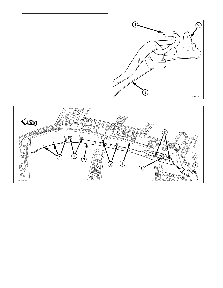
5. Remove the push pin (2) and unhook (1) the rear

tether (3) from the D-pillar.

6. Remove the screws (2) that secure the curtain airbag (3) to the spring nuts in the roof side rail (4).

7. The curtain airbag will be held in place with push pins (1). Release the push pins and remove bag (3) from

vehicle.

INSTALLATION

NOTE: When replacing a curtain airbag because of deployment, the headliner must be replaced as well,
including any damaged interior components.

PM

RESTRAINTS - SERVICE INFORMATION

8O - 365

1. Position the curtain airbag in vehicle along roof side rail (4) and install by fastening to roof side rail with integral

push fasteners (1).

2. Install the bolts (2) holding the curtain to the roof side rail. Tighten bolts to 8 N·m (71 in. lbs.).

3. Clip the front tether (2) to the A-pillar (1) and

secure push fastener.

8O - 366

RESTRAINTS - SERVICE INFORMATION

PM

4. Clip the rear tether (3) hook (1) to the D-pillar and

secure push fastener (2).

5. Connect the curtain airbag squib connector (2) to

the inflator (1).

6. Install the headliner into the vehicle (Refer to 23 -

BODY/INTERIOR/HEADLINER - INSTALLATION).

WARNING: Do not connect the battery negative
cable (Refer to 8 - ELECTRICAL/RESTRAINTS -
DIAGNOSIS AND TESTING - AIRBAG SYSTEM).
Personal injury or death may result if the system
test is not performed first.

PM

RESTRAINTS - SERVICE INFORMATION

8O - 367

DRIVER AIRBAG

DESCRIPTION

The driver airbag protective trim cover (1) is the most
visible part of the driver airbag system.

The driver airbag trim cover is held in place by a latch
and hook system (1). The driver airbag is mounted
directly to the steering wheel by two bolts on either
side of the airbag (3). Located under the airbag cover
are the folded airbag cushion, the igniter and two
squib connectors (2), the inflator, and the airbag cush-
ion supporting components. The driver airbag is a mul-
tistage-type that is designed to deploy with less force
than those used in some prior models. A radial deploy-
ing fabric airbag cushion with internal tethers is used.
The airbag inflator is a dual-initiator, non-azide, pyro-
technic-type unit. Two keyed and color-coded connec-
tor receptacles on the driver airbag inflator connect
the two inflator initiators to the vehicle electrical sys-
tem through two yellow-jacketed, two-wire pigtail har-
nesses of the clockspring.

The driver airbag cannot be repaired, and must be
replaced if deployed or in any way damaged. The
driver airbag trim cover may be disassembled from the
driver airbag unit, and is available for individual ser-
vice replacement.

OPERATION

The multistage driver airbag is deployed by electrical signals generated by the Occupant Restraint Controller (ORC)
through the driver airbag squib 1 and squib 2 circuits to the two initiators in the airbag inflator. By using two initi-
ators, the airbag can be deployed at multiple levels of force. The force level is controlled by the ORC to suit the
monitored impact conditions by providing one of four delay intervals between the electrical signals provided to the
two initiators. The longer the delay between these signals, the less forcefully the airbag will deploy.

When the ORC sends the proper electrical signals to each initiator, the electrical energy generates enough heat to
initiate a small pyrotechnic charge which, in turn ignites chemical pellets within the inflator. Once ignited, these
chemical pellets burn rapidly and produce a large quantity of inert gas. The inflator is sealed to the back of the
airbag housing and a diffuser in the inflator directs all of the inert gas into the airbag cushion, causing the cushion
to inflate. As the cushion inflates, the driver airbag trim cover will split at predetermined breakout lines, then fold
back out of the way along with the horn switch and tray unit. Following an airbag deployment, the airbag cushion

8O - 368

RESTRAINTS - SERVICE INFORMATION

PM


Content   ..  490  491  492  493   ..