Dodge Caliber. Manual - part 341


  Index      Dodge     Dodge Caliber - service repair manual 2007 year


Search            


Content   ..  339  340  341  342   ..


Dodge Caliber. Manual - part 341


ACCESSORY SWITCH BANK MODULE
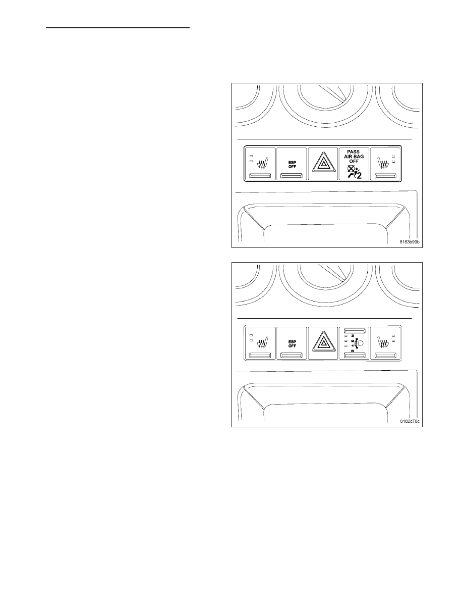
DESCRIPTION

There is an Accessory Switch Bank Module (ASBM)
located in the instrument panel center stack just below
the heater a/c control. Included in this switch bank
are:

Electronic Stability Program (ESP)/Traction Con-
trol Switch (TCS) Off (if equipped) - (Refer to 5 -
BRAKES/ELECTRICAL/ESP

SWITCH

-

DESCRIPTION)

Hazard Switch (all models) - (Refer to 8 - ELEC-
TRICAL/LAMPS/LIGHTING

-

EXTERIOR/HAZ-

ARD SWITCH - DESCRIPTION)

Heated Seat Switch (if equipped) - (Refer to 8 -
ELECTRICAL/HEATED SEATS/SEAT SWITCH -
DESCRIPTION)

Passenger Airbag Disabled Lamp (PADL) Indica-
tor (if equipped with OCS) - (Refer to 8 - ELEC-
TRICAL/RESTRAINTS - DESCRIPTION).

The BUX version of the ASBM will vary from the
domestic a bit. Following are the various BUX
switches:

Anti-Skid Control (ASC) (if equipped) - This is the
same as the ESP/TCS off switch in the domestic
version.

Hazard Switch (all models)

Heated Seat Switch (if equipped)

Headlamp Leveling Switch (if equipped) - (Refer
to 8 - ELECTRICAL/LAMPS/LIGHTING - EXTE-
RIOR/HEADLAMP

LEVELING

SWITCH

-

DESCRIPTION)

Each individual switch is not available for service replacement. If one or more switches are inoperative, the entire
ASBM must be replaced (Refer to 8 - ELECTRICAL/INSTRUMENT CLUSTER/ACCESSORY SWITCH BANK MOD-
ULE - REMOVAL). To diagnose the ASBM switches, use a scan tool and the appropriate diagnostic information.

OPERATION

For more information on the individual switches refer to the owners manual in the vehicles glove box.

PM

INSTRUMENT CLUSTER - SERVICE INFORMATION

8J - 57

REMOVAL

1. Disconnect and isolate the battery negative cable.

2. Remove the instrument panel center bezel (Refer

to

23

-

BODY/INSTRUMENT PANEL/INSTRU-

MENT PANEL CENTER BEZEL - REMOVAL).

3. Remove the screws to the Accessory Switch Bank

Module (ASBM) (4).

INSTALLATION

1. Position

the

Accessory

Switch

Bank

Module

(ASBM) (4) in the center bezel.

2. Install the screws to the ASBM.

3. Install the instrument panel center bezel (Refer to

23 - BODY/INSTRUMENT PANEL/INSTRUMENT
PANEL CENTER BEZEL - INSTALLATION).

4. Connect the battery negative cable.

8J - 58

INSTRUMENT CLUSTER - SERVICE INFORMATION

PM

CLUSTER MASK/LENS

REMOVAL

The mask and lens are serviced together as a unit. If
replacement is required for either of these compo-
nents, they both will be replaced as a unit.

1. Remove instrument cluster (Refer to 8 - ELECTRI-

CAL/INSTRUMENT CLUSTER - REMOVAL).

NOTE: You must separate the cluster bezel from
the cluster to remove the mask/lens.

2. To separate the mask/lens from the cluster hous-

ing, remove the four screws (1) along the bottom
back of the cluster and the two top screws (1).

INSTALLATION

The mask and lens are serviced together as a unit. If
replacement is required for either of these compo-
nents, they both will be replaced as a unit.

1. Position the mask/lens on the cluster housing,

install the four screws (1) along the bottom back of
the cluster and the two top screws (1).

2. Install the instrument cluster (Refer to 8 - ELEC-

TRICAL/INSTRUMENT

CLUSTER

-

INSTALLATION).

PM

INSTRUMENT CLUSTER - SERVICE INFORMATION

8J - 59


Content   ..  339  340  341  342   ..