Dodge Caliber. Manual - part 339


  Index      Dodge     Dodge Caliber - service repair manual 2007 year


Search            


Content   ..  337  338  339  340   ..


Dodge Caliber. Manual - part 339


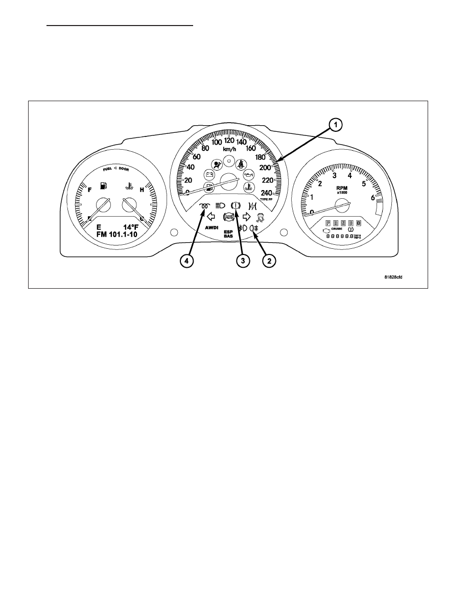
Traction Control Indicator (20)

Transmission Over Temperature Indicator (CVT transmission only) (30)

Turn Signal (Right and Left) Indicators (21)

BUX CLUSTER/CCN

The BUX CCN is relatively the same as domestic for the exception of:

Brake Fail/Park Brake Indicator (3)

Rear Fog lamps Indicator (2)

Speedometer - Kilometers per hour (km/h) (1)

Wait to Start Indicator (diesel only) (4)

OPERATION

The ElectroMechanical Instrument Cluster (EMIC) in this model also includes the hardware and software necessary
to serve as the electronic body control module and is sometimes referred to as the Cab Compartment Node or
CCN. The following information deals primarily with the instrument cluster functions of this unit. Additional details of
the electronic body control functions of this unit may be found within the service information for the system or com-
ponent that the CCN controls. For example: Additional details of the audible warning functions of the CCN are found
within the Chime/Buzzer service information.

The CCN is designed to allow the vehicle operator to monitor the conditions of many of the vehicle components and
operating systems. The gauges and indicators in the CCN provide valuable information about the various standard
and optional powertrains, fuel and emissions systems, cooling systems, lighting systems, safety systems and many
other convenience items. The CCN is installed in the instrument panel so that all of these monitors can be easily
viewed by the vehicle operator when driving, while still allowing relative ease of access for service.

The microprocessor-based CCN hardware and software uses various inputs to control the gauges and indicators
visible on the face of the cluster. Some of these inputs are hard wired, but most are in the form of electronic mes-
sages that are transmitted by other electronic modules over the Controller Area Network (CAN) data bus and the
Local Interconnect Network (LIN) data bus. The CCN is the master of the LIN bus and there are four modules that
talk to the CCN: The Heated Seat Module (HSM), Remote Compass Module (RCM), Steering Control Module
(SCM), and the Accessory Switch Bank Module (ASBM) (Refer to 8 - ELECTRICAL/ELECTRONIC CONTROL
MODULES/COMMUNICATION - OPERATION).

The CCN microprocessor smooths the input data using algorithms to provide gauge readings that are accurate,
stable and responsive to operating conditions. These algorithms are designed to provide gauge readings during
normal operation that are consistent with customer expectations. However, when abnormal conditions exist such as
high coolant temperature, the algorithm can drive the gauge pointer to an extreme position and the microprocessor

PM

INSTRUMENT CLUSTER - SERVICE INFORMATION

8J - 49

can sound a chime through the on-board audible tone transducer to provide distinct visual and audible indications of
a problem to the vehicle operator. The CCN may also produce audible warnings for other electronic modules in the
vehicle based upon electronic tone request messages received over the CAN/LIN data bus. Each audible warning is
intended to provide the vehicle operator with an audible alert to supplement a visual indication.

The CCN circuitry operates on battery current received through a fused B(+) fuse on a non-switched fused B(+)
circuit, and on battery current received through a fused ignition switch output (run-start) fuse on a fused ignition
switch output (run-start) circuit. This arrangement allows the/CCN to provide some features regardless of the ignition
switch position, while other features will operate only with the ignition switch in the On or Start positions. The CCN
circuitry is grounded through a ground circuit of the instrument panel wire harness.

The CCN also has a self-diagnostic actuator test capability which will test each of the CAN bus message-controlled
functions of the cluster by lighting the appropriate indicators, positioning the gauge needles at several predeter-
mined calibration points across the gauge faces, and illuminating all segments of the odometer/trip odometer/gear
selector indicator Vacuum-Fluorescent Display (VFD) unit and Electronic Vehicle Information Center (EVIC). The
EVIC will display the hardware/software version, and the CAN and LIN Vehicle Maintenance Monitor (VMM) used in
the CCN. (Refer to 8 - ELECTRICAL/INSTRUMENT CLUSTER - DIAGNOSIS AND TESTING).

The CCN collects data and provides control signals for the following electrical equipment via the CAN data bus:

Gauges

Interior lighting controls

Variable-intensity cluster lighting and illumination of instrument panel mounted equipment

Vehicle Theft Alarm and Sentry Key Theft Deterrent System

Power door lock system controls (automatic locking, and Remote Keyless Entry locking and unlocking)

Headlamp switch actuation signal

Steering wheel radio actuation signals

Accessory power delay relay control

Wiper control

Turn signal flasher audible click

Heated seat actuation signal (if equipped)

UConnect

T

Hands-Free, Voice-Actuated Communication system actuation signal (if equipped)

Display of the outputs for the HomeLink

T

universal home security system and compass (if equipped)

Illuminated entry system

Key-in-ignition warning chime

Seat belt warning chime and lamp (Including BeltAlert

T

)

Low washer fluid warning indicator

Door ajar warning indicator

Liftgate/trunk ajar warning indicator

LIN master module

The CCN also provides the following enhancements to the above features:

Time-out for interior lamps left on inadvertently

Driver programmability of vehicle speed-sensitive automatic locking

Driver programmability of the power locks to unlock only the driver’s door or all doors with the first actuation of
the RKE unlock button

Ability to program vehicle response to lock and unlock commands from the RKE transmitter

The improved BeltAlert

T

seatbelt warning indication

Filtering of input signals to the fuel gauge, temperature gauge, and speedometer to avoid sudden, unexpected
pointer movements

Headlamp control for turning the headlamps on if the windshield wipers are operated in daylight as required by
law in some states

GAUGES

All gauges receive battery current through the CCN circuitry only when the ignition switch is in the On or Start
positions. With the ignition switch in the Off position battery current is not supplied to any gauges, and the CCN
circuitry is programmed to move all of the gauge needles back to the low end of their respective scales. Therefore,
the gauges do not accurately indicate any vehicle condition unless the ignition switch is in the On or Start positions.

8J - 50

INSTRUMENT CLUSTER - SERVICE INFORMATION

PM

All of the CCN gauges are stepper motors. The gauges are diagnosed using the CCN self-diagnostic actuator test.
(Refer to 8 - ELECTRICAL/INSTRUMENT CLUSTER - DIAGNOSIS AND TESTING). Proper testing of the CAN data
bus and the electronic data bus message inputs to the CCN that control each gauge require the use of a diagnostic
scan tool. Refer to the appropriate diagnostic information. Specific operation details for each gauge may be found
elsewhere in this service information.

VACUUM-FLUORESCENT DISPLAYS

ODOMETER/TRIP ODOMETER - The odometer and trip odometer give an indication to the vehicle operator of the
distance the vehicle has traveled. The engine hours give an indication of the cumulative engine-ON time. This indi-
cator is controlled by the instrument cluster circuitry based upon cluster programming and electronic messages
received by the cluster from the Powertrain Control Module (PCM) or Engine Control Module (ECM) over the Con-
troller Area Network (CAN) data bus.

The odometer/trip odometer will display some warning messages such as “d00R” and “gATE” ajar. If equipped with
the optional Electronic Vehicle Information Center (EVIC), the EVIC will display all messages except GASCAP.

The odometer, trip odometer and engine hours information are displayed by the instrument cluster Vacuum Fluo-
rescent Display (VFD). The VFD will display the odometer information whenever the driver side front door is opened
with the ignition switch in the OFF or ACCESSORY positions, and will display the last previously selected odometer
or trip odometer information when the ignition switch is turned to the ON or START positions. The instrument cluster
circuitry controls the VFD and provides the following features:

Odometer/Trip Odometer Display Toggling - Actuating the trip odometer reset switch button momentarily
with the VFD illuminated will toggle the display between the odometer and trip odometer information. Each
time the VFD is illuminated with the ignition switch in the ON or START positions, the display will automatically
return to the last mode previously selected (odometer or trip odometer).

Engine Hours Display Toggling - When the trip odometer reset switch button is pressed and held for longer
than about six seconds with the ignition switch in the ON position and the engine speed message from the
PCM is zero, the trip odometer information will be momentarily displayed, then the engine hours information
will be displayed. The VFD must be displaying the odometer information when the trip odometer reset switch
button is pressed in order to toggle to the engine hours display. The engine hours will remain displayed for
about 30 seconds, until the engine speed message is greater than zero, or until the ignition switch is turned to
the OFF position, whichever occurs first.

Trip Odometer Reset - When the trip odometer reset switch button is pressed and held for longer than about
two seconds with the ignition switch in the ON or START position, the trip odometer will be reset to 0.0 kilo-
meters (miles). The VFD must be displaying the trip odometer information in order for the trip odometer infor-
mation to be reset.

GASCAP Message Display - On vehicles manufactured with a United States country code, each time the
cluster receives an electronic message from the PCM indicating a monitored leak in the evaporative emissions
system, the cluster replaces the displayed odometer/trip odometer value with the textual message, GASCAP.
This message serves as a reminder to the vehicle operator to check that the gas cap is properly installed and
tightened, but could also indicate another source of air leakage in the on-board evaporative and vapor recov-
ery emissions systems. Unless the leak is corrected, this message will latch and remain displayed during the
current and each subsequent ignition cycle until the trip odometer reset button is pressed and released
momentarily, which will revert the display to the odometer/trip odometer information that was last displayed for
the remainder of that ignition cycle. Once the source of a leak has been corrected, either momentarily pressing
the trip odometer reset button or cycling the ignition switch will unlatch the message and return the odometer/
trip odometer to normal operation.

Communication Error - If the cluster fails to receive an electronic distance message during normal operation,
it will hold and display the last data received until the ignition switch is turned to the OFF position. If the cluster
does not receive a distance message within one second after the ignition switch is turned to the ON position,
it will display the last distance value stored in the cluster memory. If the cluster is unable to display distance
information due to an error internal to the cluster, the VFD will display Error.

Actuator Test - Each time the cluster is put through the actuator test, the odometer VFD will display all of its
segments simultaneously, then step through each character segment individually during the VFD portion of the
test to confirm the functionality of the VFD and the cluster control circuitry.

The PCM continually monitors the vehicle speed pulse information received from the Vehicle Speed Sensor (VSS)
or the Controller Anti-lock Brake (CAB) and engine speed pulse information received from the crankshaft position
sensor, then sends the proper messages to the ElectroMechanical Instrument Cluster (EMIC). For further diagnosis

PM

INSTRUMENT CLUSTER - SERVICE INFORMATION

8J - 51

of the odometer/trip odometer or the instrument cluster circuitry that controls these functions, (Refer to 8 - ELEC-
TRICAL/INSTRUMENT CLUSTER - DIAGNOSIS AND TESTING).

For proper diagnosis of the VSS, the crankshaft position sensor, the CAB, the PCM, the EMIC, the CAN data bus
or the electronic communication related to odometer/trip odometer operation a diagnostic scan tool is required.
Refer to the appropriate diagnostic information.

ELECTRONIC VEHICLE INFORMATION CENTER DISPLAY - The Electronic Vehicle Information Center (EVIC)
features a driver-interactive display. The display is located in the lower left part of the instrument cluster below the
fuel and engine temperature gauges. This system conveniently allows the driver to select a variety of useful infor-
mation by pressing the STEP button to the right of the EVIC display. The EVIC displays information related to the
following:

Audio mode display

Compass display

Navigation system screens (if equipped)

Outside temperature display

Personal Settings (customer programmable features)

System Status

Trip computer functions

UConnect™ hands-free communication system displays (if equipped)

Vehicle information warning message displays

The Vacuum-Fluorescent Display (VFD) units are soldered to the CCN electronic circuit board. With the ignition
switch in the Off or Accessory positions, the left and right VFD displays are activated when the driver door is
opened and is deactivated when the driver door is closed. Otherwise, the display units are active when the ignition
switch is in the On or Start positions, and inactive when the ignition switch is in the Off or Accessory positions.

The illumination intensity of the VFD units are controlled by the CCN circuitry based upon an input from the head-
lamp switch and a dimming level input received from the panel dimmer switch. The CCN synchronizes the illumi-
nation intensity of other VFD units with that of the unit in the CCN by sending electronic dimming level messages
to other electronic modules in the vehicle over the CAN/LIN data bus.

The CCN VFD units have several display capabilities. The right VFD unit displays odometer, trip odometer, engine
hours, gear selector indication (PRNDL) for models with an automatic transmission, several warning or reminder
indications, and various diagnostic information when certain fault conditions exist. An odometer/trip odometer switch
on the CCN circuit board is used to control some of the display modes of the right VFD. This switch is actuated
manually by depressing the odometer/trip odometer switch button that extends through the lower edge of the cluster
lens, just left of the tachometer. Actuating this switch momentarily with the ignition switch in the On position will
toggle the VFD between the odometer and trip odometer modes. Depressing the switch button for about two sec-
onds while the VFD is in the trip odometer mode will reset the trip odometer value to zero. The left VFD unit dis-
plays the Electronic Vehicle Information Center (EVIC) and Compass/Temperature information. The left switch button
is used as a STEP button for the EVIC display and customer programmable features (Refer to 8 - ELECTRICAL/
MESSAGE CENTER/ELECT VEHICLE INFORMATION CENTER - OPERATION).

NOTE: If the vehicles OnBoard Diagnostic (OBD) system determines that the fuel filler cap is loose, improp-
erly installed, or damaged, a “GASCAP” message will be displayed in the Odometer/Trip Odometer. In this
instance, tighten the fuel filler cap and press the odometer/trip odometer reset button once to turn the mes-
sage OFF. The key must be in the Run/Start position during the reset, or you may just cycle the key. If left
loose for three trips, or key cycles, a DTC will set and the MIL lamp will illuminate.

Holding the right switch depressed while turning the ignition switch from the Off position to the On position will
initiate the CCN self-diagnostic actuator test. Refer to the instrument cluster diagnosis and testing service informa-
tion for additional details on this cluster function. The CCN microprocessor remembers which display mode is active
when the ignition switch is turned to the Off position, and returns the VFD display to that mode when the ignition
switch is turned On again.

The VFD unit is diagnosed using the CCN self-diagnostic actuator test. (Refer to 8 - ELECTRICAL/INSTRUMENT
CLUSTER - DIAGNOSIS AND TESTING). Proper testing of the CAN data bus and the electronic data bus message
inputs to the CCN that control some of the VFD functions requires the use of a diagnostic scan tool. Refer to the
appropriate diagnostic information. Specific operation details for the odometer, the trip odometer, the gear selector
indicator and the various warning and reminder indicator functions of the VFD unit may be found elsewhere in this
service information. Refer to the vehicle owners manual for further information on various readout messages.

8J - 52

INSTRUMENT CLUSTER - SERVICE INFORMATION

PM


Content   ..  337  338  339  340   ..