Dodge Caliber. Manual - part 304


  Index      Dodge     Dodge Caliber - service repair manual 2007 year


Search            


Content   ..  302  303  304  305   ..


Dodge Caliber. Manual - part 304


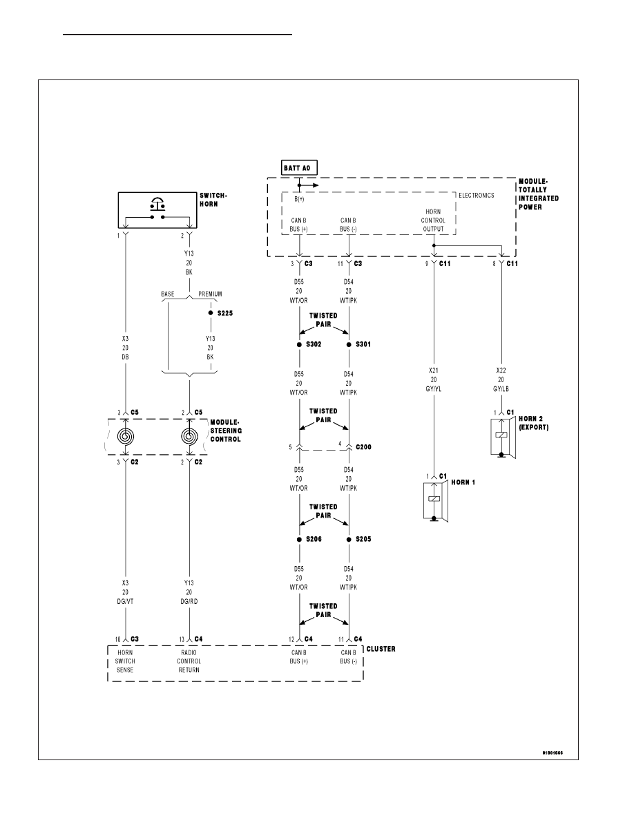
B2336–HORN CONTROL CIRCUIT LOW (TIPM)

For a complete wiring diagram Refer to Section 8W.

PM

HORN SYSTEM - ELECTRICAL DIAGNOSTICS

8H - 3

When Monitored:
With the ignition on. Battery voltage greater than 10.4 volts.

Set Condition:
A shorted low condition on the (X21)/(X22) Horn Control Output circuit.

Possible Causes

(X21) HORN CONTROL OUTPUT CIRCUIT SHORTED TO GROUND

(X22) HORN CONTROL OUTPUT CIRCUIT SHORTED TO GROUND (EXPORT)

TIPM

Diagnostic Test

1.

VERIFY DTC B2336–HORN CONTROL CIRCUIT LOW IS ACTIVE

With the scan tool, erase TIPM DTCs.

Operate the Horn Switch several times.

With the scan tool, read TIPM DTCs.

Does the scan tool display active DTC B2336-HORN CONTROL CIRCUIT LOW?

Yes

>> Go To 2

No

>> Check for an intermittent condition by inspecting the related wiring harness for chafed, pierced, pinched,

and partially broken wires. Also, inspect the related connectors for broken, bent, corroded, or contami-
nated terminals.

Perform BODY VERIFICATION TEST - VER 1. (Refer to 8 - ELECTRICAL/ELECTRONIC CONTROL
MODULES - STANDARD PROCEDURE)

2.

(X21)/(X22) HORN CONTROL OUTPUT CIRCUIT SHORTED TO GROUND

Turn the ignition off

Disconnect the horn connector(s).

Disconnect the C11 TIPM harness connector.

Measure the resistance between ground and the Horn Control Output
circuit(s) at the horn connector(s).

Is the resistance below 100 ohms?

Yes

>> Repair the (X21)/(X22) Horn Control Output circuit for a

short to ground.

Perform the BODY VERIFICATION TEST – VER 1. (Refer
to 8 - ELECTRICAL/ELECTRONIC CONTROL MODULES -
STANDARD PROCEDURE)

No

>> Go To 3

8H - 4

HORN SYSTEM - ELECTRICAL DIAGNOSTICS

PM

3.

HORN

Connect the C11 TIPM harness connector.

Turn the ignition on, engine not running.

Using the scan tool under the TIPM Actuators, actuate the Horn.

With a 12-volt test light connected to ground, probe the Horn Control
Output circuit at the Horn connector(s).

Does the test light illuminate brightly and flash on and off?

Yes

>> Replace the Horn(s) as necessary per Service Information.

Perform the BODY VERIFICATION TEST – VER 1. (Refer
to 8 - ELECTRICAL/ELECTRONIC CONTROL MODULES -
STANDARD PROCEDURE)

No

>> Go To 4

4.

TOTALLY INTEGRATED POWER MODULE

NOTE: Before continuing, check the TIPM harness connector terminals for corrosion, damage, or terminal
push out. Repair as necessary.
Using the schematics as a guide, inspect the wire harness and connectors.

Pay particular attention to all Power and Ground circuits.

Were any problems found?

Yes

>> Repair as necessary.

Perform the BODY VERIFICATION TEST – VER 1. (Refer to 8 - ELECTRICAL/ELECTRONIC CON-
TROL MODULES - STANDARD PROCEDURE)

No

>> Replace the Totally Integrated Power Module per Service Information.

Perform the BODY VERIFICATION TEST – VER 1. (Refer to 8 - ELECTRICAL/ELECTRONIC CON-
TROL MODULES - STANDARD PROCEDURE)

PM

HORN SYSTEM - ELECTRICAL DIAGNOSTICS

8H - 5

B2337–HORN CONTROL CIRCUIT HIGH (TIPM)

For a complete wiring diagram Refer to Section 8W

8H - 6

HORN SYSTEM - ELECTRICAL DIAGNOSTICS

PM


Content   ..  302  303  304  305   ..