Dodge Caliber. Manual - part 302


  Index      Dodge     Dodge Caliber - service repair manual 2007 year


Search            


Content   ..  300  301  302  303   ..


Dodge Caliber. Manual - part 302


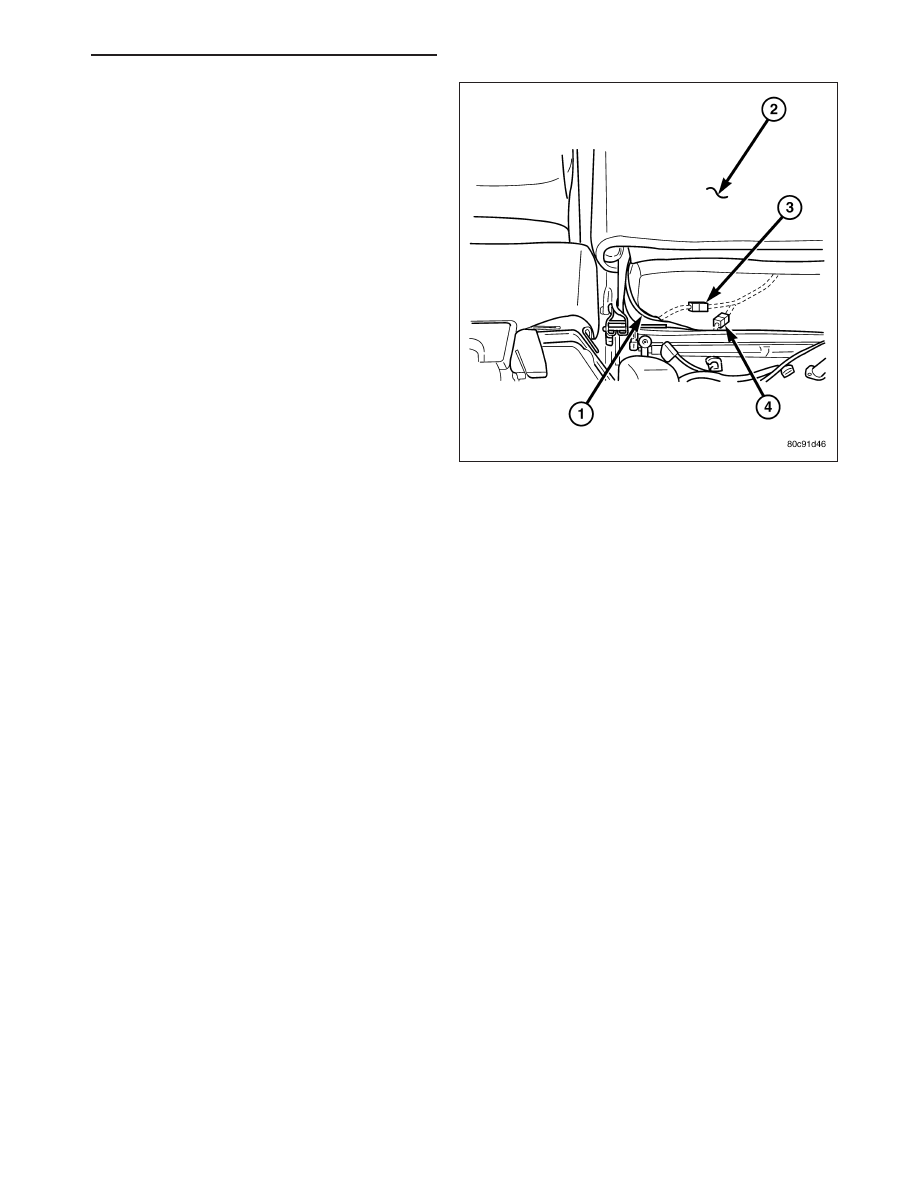
2. Connect the new heating element electrical con-

nectors (3&4).

3. Connect the battery negative cable.

4. Verify heated seat system operation.

5. Install the appropriate seat cushion, (Refer to 23 -

BODY/SEATS/SEAT CUSHION COVER - INSTAL-
LATION) or seat back trim cover, (Refer to 23 -
BODY/SEATS/SEAT BACK CUSHION / COVER -
INSTALLATION).

NOTE: Make certain the seat wire harness is cor-
rectly routed through the seat and seat back. The
excess wire between the cushion and back ele-
ments should be securely tucked between the rear
of the cushion foam and the rear carpet flap of the
trim cover.

PM

HEATED SEATS - SERVICE INFORMATION

8G - 63

MODULE-HEATED SEATS

DESCRIPTION

The heated seat module (2) is located under the left
front seat. It has a single electrical connector (1) and
a push pin style retainer that secures it to the seat
pan. The module can be accessed from under the
front left seat with the seat in the full back position.

The heated seat module is a microprocessor designed
to use the Local Interface Network (LIN) data bus
messages from the instrument cluster also known as
the Cabin Compartment Node (CCN). The CCN
receives inputs from the heated seat switches and in
turn signals the heated seat module to operate the
heated seat elements for both front seats.

OPERATION

The heated seat module operates on fused battery current received from the ignition switch. The module is
grounded to the body at all times through the electrical connector. Inputs to the module include Local Interface
Network (LIN) data bus messages and standard hardwired 12 volt power and ground. In response to the LIN inputs
the heated seat module will control the battery current to the appropriate heated seat elements.

When a heated seat switch LIN data bus signal is received by the heated seat module, the module energizes the
selected heated seat element. The Low heat set point is about 38°C (100.4°F), and the High heat set point is about
42°C (107.6°F).

In addition to operating the heated seat elements, the heated seat module sends LED illumination messages to the
CNN via the LIN data bus. The CNN then sends the LED illumination message to the accessory switch bank so that
the appropriate LEDs are illuminated for any given heating level. Pressing the switch once will select high-level
heating. Pressing the switch a second time will select low-level heating. Pressing the switch a third time will shut the
heating elements off.

If the heated seat module detects a heated seat element OPEN or SHORT circuit, it will record and store the appro-
priate diagnostic trouble code (DTC).

DIAGNOSIS AND TESTING

HEATED SEAT MODULE

In order to obtain conclusive testing, the heated seat system and the Local Interface Network (LIN) data bus circuit
must be checked. Any diagnosis of the heated seat system should begin with, the use of a scan tool and the
appropriate diagnostic service information.

Refer to the appropriate wiring information for complete circuit schematic or connector pin-out information.

NOTE: Vehicles equipped with the heated seat option utilize a low voltage cut-off feature. This feature turns
off power to the heated seat system anytime vehicle voltage is below 11.7v or above 15.5v. Be certain to
check the vehicle electrical system for proper voltage anytime the power seat system appears inoperative.

Before any testing of the heated seat system is attempted, the battery should be fully-charged.

8G - 64

HEATED SEATS - SERVICE INFORMATION

PM

REMOVAL

CAUTION: The Heated Seat Module mounting tab
can be damaged during module removal and
installation. Use care to properly align tab to pre-
vent binding that could result in tab breakage.

1. Position the right front seat to the full rearward

position.

2. Disconnect and isolate the battery negative cable.

3. Disconnect the wire harness connector (4) from the

heated seat module (3).

4. Unsnap the heated seat module retaining tab (2)

from the seat pan (1).

5. Remove the heated seat module (3) from the

vehicle.

INSTALLATION

CAUTION: The Heated Seat Module mounting tab can be damaged during module removal and installation.
Use care to properly align tab to prevent binding that could result in tab breakage.

1. Install the heated seat module (3) into the vehicle.

2. Position the retaining tab (2) with the mounting

hole in the seat pan (1). Firmly apply even pres-
sure to the module (3) until the mounting tab is
fully seated.

3. Connect the wire harness connector (4) to the

heated seat module (3).

4. Connect the battery negative cable.

5. Check for proper heated seat system operation.

PM

HEATED SEATS - SERVICE INFORMATION

8G - 65

SWITCH-HEATED SEAT

DESCRIPTION

The heated seat switches are located in the center
stack (1) of the instrument panel. The switches are
located on the outer edges of the accessory switch
bank (2). If either of the switches is damaged or inop-
erative the complete accessory switch bank assembly
must be replaced.

When

either

of

the

heated

seat

switches

are

depressed a switch status message is sent to the Cab
Compartment Node (CCN) or instrument cluster via
the Local Interface Network (LIN) data bus. The CCN
then sends a message via the LIN data bus to the
heated seat module, signaling the module to energize
the heating element for the selected seat. Amber Light
Emitting Diodes (LEDs) in the top portion of each
switch indicate the level of heat in use: Two LEDs are
illuminated for high, one for low, and none for off. The
heated seat module sends the LED illumination mes-
sage to the CNN via the LIN data bus. The CNN then
sends the LED illumination message to the accessory switch bank so that the appropriate LEDs are illuminated for
any given heating level. Pressing the switch once will select high-level heating. Pressing the switch a second time
will select low-level heating. Pressing the switch a third time will shut the heating elements off.

The LED indicator lamps in each heated seat switch cannot be repaired. If the LED lamps are inoperative or dam-
aged, or the switch is inoperative or damaged the complete accessory switch bank assembly must be replaced.

OPERATION

The heated seat switches are active any time the Local Interface Network (LIN) data bus is active. Depressing the
heated seat switch provides a switch status message to the Cabin Compartment Node (CCN) via the LIN data bus.
The CCN is responsible for supplying the LIN data bus message to the heated seat module, signaling the module
to power the heated seat element of the selected seat and maintain the temperature setting. If the heated seat
switch is depressed to a different position (Low or High) than the currently selected state, the CCN will go through
the process again to change the temperature setting.

DIAGNOSIS AND TESTING

HEATED SEAT SWITCH

In order to obtain conclusive testing, the heated seat system and the Local Interface Network (LIN) data bus circuit
must be checked. Any diagnosis of the heated seat system should begin with, the use of a scan tool and the
appropriate diagnostic service information.

Refer to the appropriate wiring information for complete circuit schematic or connector pin-out information.

NOTE: Vehicles equipped with the heated seat option utilize a low voltage cut-off feature. This feature turns
off power to the heated seat system anytime vehicle voltage is below 11.0v or above 15.5v. Be certain to
check the vehicle electrical system for proper voltage anytime the power seat system appears inoperative.

Before any testing of the heated seat system is attempted, the battery should be fully-charged.

8G - 66

HEATED SEATS - SERVICE INFORMATION

PM


Content   ..  300  301  302  303   ..