Dodge Caliber. Manual - part 164
INSTALLATION
1. Clean the surfaces of the flywheel and pressure
plate to make certain that all oil, grease, and rust
have been removed.
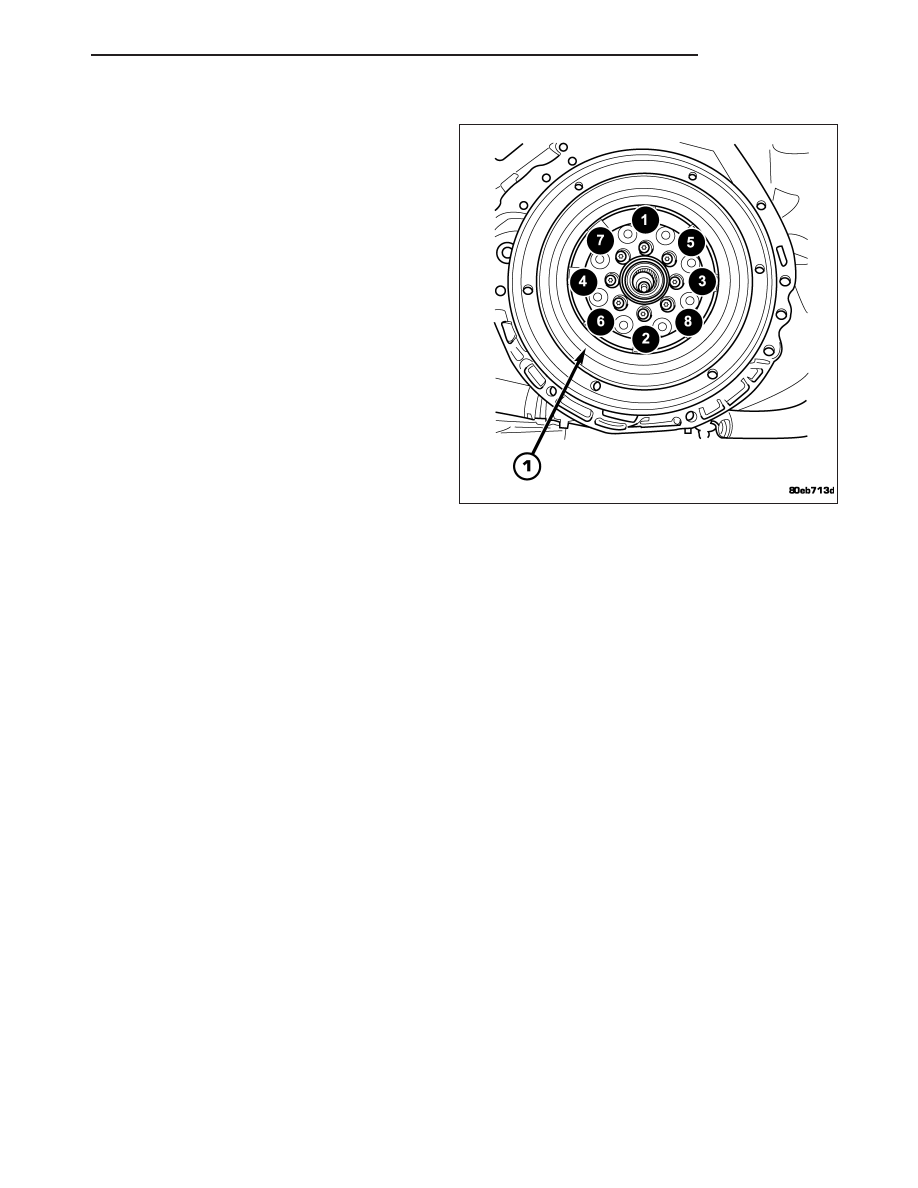
2.
Install and torque the flywheel-to-crankshaft bolts
to 95 N·m (70 ft.lbs.).
3. Install clutch pressure plate and disc (Refer to 6 -
CLUTCH/CLUTCH DISC - INSTALLATION).
4. Install transaxle assembly (Refer to 21 - TRANS-
MISSION/TRANSAXLE/MANUAL
-
INSTALLATION).
PM
CLUTCH
6 - 15