Dodge Caliber. Manual - part 163


  Index      Dodge     Dodge Caliber - service repair manual 2007 year


Search            


Content   ..  161  162  163  164   ..


Dodge Caliber. Manual - part 163


GAS

1. Remove transaxle assembly (Refer to 21 - TRANS-

MISSION/TRANSAXLE/MANUAL - REMOVAL).

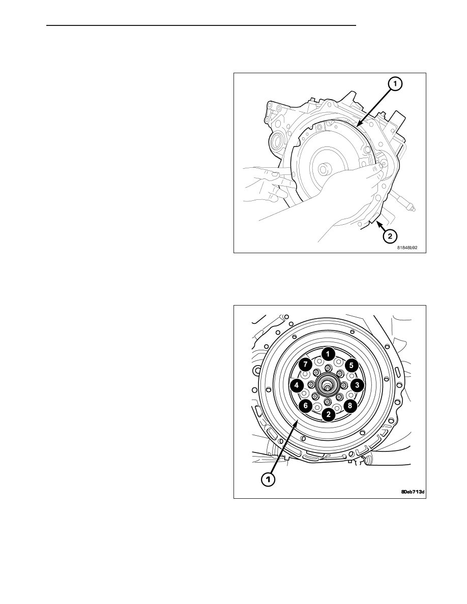
2. Remove the modular clutch assembly (1).

INSTALLATION

DIESEL

1. Inspect clutch release bearing and lever for exces-

sive wear and replace as necessary. The release
bearing is integral to the Concentric Slave Cylinder
(CSC).

2. Clean the surfaces of the flywheel (1) and pressure

plate to make certain that all oil, grease, and rust
have been removed.

3. Verify the crankshaft mounting flange is free of

debris, oil, grease, etc. Position the flywheel (1)
onto the engine crankshaft.

4. Install flywheel to crankshaft. Install eight (8) fly-

wheel-to-crankshaft bolts and torque to 45 N·m (33
ft. lbs.) plus an additional

1

4

turn (90°).

PM

CLUTCH

6 - 11

5. Apply a very light coating of grease to the splines

in the clutch disc hub.

6. Position the clutch disc (2) to the flywheel (1).

Make sure the side marked “FLYWHEEL SIDE”
faces the flywheel (1).

7. Install the clutch pressure plate (1) to the flywheel

and clutch disc. Finger tighten the six pressure
plate-to-flywheel bolts.

8. Use Clutch Alignment Tool 6724 (3) to position the

clutch disc (2) to the center of the flywheel (1).

9. Tighten pressure plate bolts (2) evenly and in rota-

tion a few threads at a time The bolts must be
tightened evenly and to specified torque to
avoid distorting the pressure plate.

10. Using a “criss-cross” pattern, torque pressure

plate bolts (2) to 31 N·m (23 ft. lbs.). Remove the
clutch disc alignment tool.

11. Apply light coat of MOPAR

T

High Temperature

Bearing Grease or equivalent to clutch disc hub
and splines of transmission input shaft.

CAUTION: Do not over lubricate shaft splines. This
will result in grease contamination of disc.

12. Install transaxle (Refer to 21 - TRANSMISSION/

TRANSAXLE/MANUAL - INSTALLATION).

6 - 12

CLUTCH

PM

GAS

1. Install new modular clutch assembly onto input

shaft of transmission.

2. Install the transmission (Refer to 21 - TRANSMIS-

SION/TRANSAXLE/MANUAL - INSTALLATION)

.

PM

CLUTCH

6 - 13

FLYWHEEL

OPERATION

The flywheel serves to dampen the engine firing pulses. The heavy weight of the flywheel relative to the rotating
mass of the engine components serves to stabilize the flow of power to the remainder of the drivetrain. The crank-
shaft has the tendency to attempt to speed up and slow down in response to the cylinder firing pulses. The flywheel
dampens these impulses by absorbing energy when the crankshaft speeds and releasing the energy back into the
system when the crankshaft slows down.

On a Dual Mass Flywheel, the additional secondary mass coupled to the transmission lowers the natural frequency
of the transmission rotating elements. This decreases the transmission gear rattle. The damper springs between the
two flywheel masses replace the clutch disc damper springs and assist in a smooth transfer of torque to the trans-
mission.

CAUTION: The Dual Mass Flywheel is serviced as an assembly only and should never be disassembled.

REMOVAL

1. Remove transaxle (Refer to 21 - TRANSMISSION/

TRANSAXLE/MANUAL - REMOVAL).

2. Remove clutch pressure plate and disc (Refer to 6

- CLUTCH/CLUTCH DISC - REMOVAL).

3. Remove eight (8) flywheel-to-crankshaft bolts (2)

and remove flywheel assembly (1).

6 - 14

CLUTCH

PM


Content   ..  161  162  163  164   ..