Dodge Caliber. Manual - part 1333


  Index      Dodge     Dodge Caliber - service repair manual 2007 year


Search            


Content   ..  1331  1332  1333  1334   ..


Dodge Caliber. Manual - part 1333


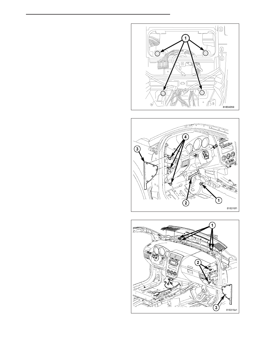
27. Remove four bolts (1) behind center bezel and

one behind glove box.

28. Remove bolts fastening Instrument panel to cowl

panel. Three bolts (4) located behind left end cap,
and one at the bottom of the instrument panel (1).

29. Remove condensation drain tube (2). (Refer to 24

- HEATING & AIR CONDITIONING/PLUMBING/
WATER VALVE - REMOVAL)

30. Remove two bolts (2) behind the left end cap and

four screws (1) located under the top cover.

PM

INSTRUMENT PANEL

23 - 69

31. Disconnect wire harness from HVAC (2).

32. With the help of assistant, remove instrument

panel through driver side door.

INSTALLATION

WARNING: On vehicles equipped with airbags, disable the airbag system before attempting any steering
wheel, steering column, or instrument panel component diagnosis or service. Disconnect and isolate the
negative battery (ground) cable, then wait two minutes for the airbag system capacitor to discharge before
performing further diagnosis or service. This is the only sure way to disable the airbag system. Failure to
take the proper precautions could result in accidental airbag deployment and possible personal injury or
death.

NOTE: Left hand drive shown. Right hand drive similar.

1. With the help of an assistant, load instrument panel

into vehicle inserting stud (2) into dash and ensur-
ing instrument panel hangs on reinforcement (2).

2. Install condensation drain tube into floor. (Refer to

24 - HEATING & AIR CONDITIONING/PLUMBING/
WATER VALVE - REMOVAL)

23 - 70

INSTRUMENT PANEL

PM

3. Connect HVAC wire harness (2).

4. Install 11 instrument panel to cowl panel fasteners.

Tighten to 21 N·m (15 ft. lbs.).

5. Install four fasteners (1) behind center bezel and

one behind glove box.

6. Install left and right floor ducts. (Refer to 24 -

HEATING & AIR CONDITIONING/PLUMBING/WA-
TER VALVE - REMOVAL)

7. Connect instrument panel center console wiring

harness.

8. Install left and right door scuff plate. (Refer to 23 -

BODY/INTERIOR/DOOR SILL TRIM - INSTALLA-
TION)

9. Install lower B - Pillar trim panels. (Refer to 23 -

BODY/INTERIOR/B-PILLAR

LOWER

TRIM

-

INSTALLATION)

10. Install B - Pillar trim panels. (Refer to 23 - BODY/

INTERIOR/B-PILLAR TRIM - INSTALLATION)

11. Install Center console. (Refer to 23 - BODY/INTE-

RIOR/CENTER CONSOLE - INSTALLATION)

12. Install left and right seats. (Refer to 23 - BODY/

SEATS/SEAT - INSTALLATION)

PM

INSTRUMENT PANEL

23 - 71

13. Connect radio harness (1) to antenna (2).

14. Install right cowl panel. (Refer to 23 - BODY/IN-

TERIOR/COWL TRIM - INSTALLATION)

15. Install glove box.

16. Connect A-Pillar (2) wiring harness (3).

17. Connect instrument panel wiring harness (1) to (2)

and (3), (7), and (5).

18. Install left cowl panel. (Refer to 23 - BODY/INTE-

RIOR/COWL TRIM - INSTALLATION)

19. Install Top Panel. (Refer to 23 - BODY/INSTRU-

MENT

PANEL/INSTRUMENT

PANEL

TOP

COVER - INSTALLATION)

20. Install left and right A - Pillar trim. (Refer to 23 -

BODY/INTERIOR/A-PILLAR TRIM - INSTALLA-
TION)

21. Install shifter assembly.

22. Install center bezel. (Refer to 23 - BODY/INSTRU-

MENT PANEL/INSTRUMENT PANEL CENTER
BEZEL - REMOVAL)

23. Install center console shifter housing. (Refer to 23

-

BODY/INTERIOR/CENTER

CONSOLE

-

INSTALLATION)

23 - 72

INSTRUMENT PANEL

PM


Content   ..  1331  1332  1333  1334   ..