Dodge Caliber. Manual - part 1249


  Index      Dodge     Dodge Caliber - service repair manual 2007 year


Search            


Content   ..  1247  1248  1249  1250   ..


Dodge Caliber. Manual - part 1249


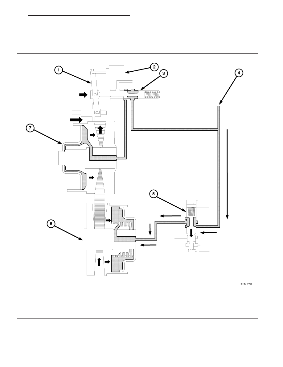
By pulling the steel belt to the primary pulley side, the moving-pulley of the secondary pulley moves to the right side
also.

SHIFT LOW TO HIGH - PHASE 4

Additionally, the sliding element of the primary pulley moves to the right direction and the ratio control valve also
moves to the right side and closes the line pressure circuit; this is a completion of the shift.

The secondary valve moves downwards to apply the line pressure to the secondary pulley in order to apply clamp-
ing force to the steel belt.

Fig. 8 SHIFT LOW TO HIGH 4

1 - PULLEY RATIO LINKAGE

5 - SECONDARY VALVE

2 - STEPPER MOTOR

6 - SECONDARY PULLEY

3 - RATIO CONTROL VALVE

7 - PRIMARY PULLEY

4 - LINE PRESSURE

PM

AUTOMATIC - CVT-SERVICE INFORMATION

21 - 295

SHIFT HIGH TO LOW - PHASE 1

The pulley ratio linkage moves to the right direction in the stepper motor. As the ratio control valve which links to the
pulley ratio linkage, moves fluid and the primary pulley is drained.

Because the secondary valve is moving downwards, line pressure is applied to the secondary pulley.

Fig. 9 SHIFTING HIGH TO LOW

1 - PULLEY RATIO LINKAGE

5 - SECONDARY VALVE

2 - STEPPER MOTOR

6 - SECONDARY PULLEY

3 - RATIO CONTROL VALVE

7 - PRIMARY PULLEY

4 - LINE PRESSURE

21 - 296

AUTOMATIC - CVT-SERVICE INFORMATION

PM

SHIFT HIGH TO LOW - PHASE 2

By applying line pressure to the secondary pulley, the sliding element moves to the left direction and the steel belt
is pushed outside.

By pulling the steel belt to the secondary pulley side, the moving-pulley of the primary pulley moves to the left side.

By actuating the “Sliding element” of the primary pulley moves to the left side, the ratio control valve starts to move
to the left side through the pulley ratio linkage which is linked to the sliding element.

Fig. 10 SHIFTING HIGH TO LOW 2

1 - PULLEY RATIO LINKAGE

5 - SECONDARY VALVE

2 - STEPPER MOTOR

6 - SECONDARY PULLEY

3 - RATIO CONTROL VALVE

7 - PRIMARY PULLEY

4 - LINE PRESSURE

PM

AUTOMATIC - CVT-SERVICE INFORMATION

21 - 297

SHIFT HIGH TO LOW - PHASE 3

Additionally, the moving-pulley of the secondary pulley moves to the left direction and the steel belt is pushed out-
side. In accordance with this, the sliding element of the primary pulley moves to the left side.

The moving-pulley of the primary pulley moves to the right direction, then the ratio control valve also moves to the
left direction and closes the drain circuit; this is a completion of the shift.

Fig. 11 SHIFTING HIGH TO LOW 3

1 - PULLEY RATIO LINKAGE

5 - SECONDARY VALVE

2 - STEPPER MOTOR

6 - SECONDARY PULLEY

3 - RATIO CONTROL VALVE

7 - PRIMARY PULLEY

4 - LINE PRESSURE

21 - 298

AUTOMATIC - CVT-SERVICE INFORMATION

PM


Content   ..  1247  1248  1249  1250   ..