Content .. 1246 1247 1248 1249 ..
Dodge Caliber. Manual - part 1248
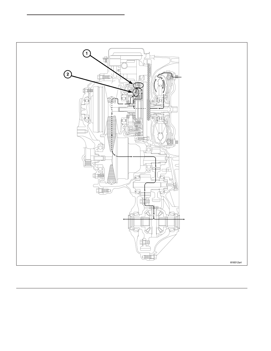
DRIVE POWERFLOW
When the forward clutch is engaged, the driving force from the engine rotates the sun gear normally through the
forward clutch.
Therefore, the primary pulley is rotated normally and the driving force is outputted in the normally rotated direction.
Fig. 4 DRIVE
1 - REVERSE BRAKE (RELEASED)
2 - FORWARD CLUTCH (ENGAGED)
PM
AUTOMATIC - CVT-SERVICE INFORMATION
21 - 291