Content .. 1211 1212 1213 1214 ..
Dodge Caliber. Manual - part 1213
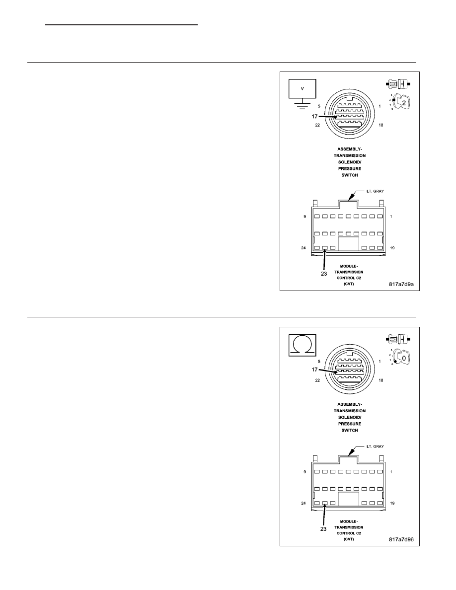
3.
CHECK THE (T54) TRANSMISSION TEMPERATURE SENSOR SIGNAL CIRCUIT FOR A SHORT TO
VOLTAGE
Turn the ignition off to the lock position.
Disconnect the TCM C2 harness connector.
Ignition on, engine not running.
Measure the voltage of the (T54) Transmission Temperature Sensor
Signal circuit.
Is the voltage above .05 volts?
Yes
>> Repair the (T54) Transmission Temperature Sensor Signal
circuit for a short to voltage.
Perform CVT VERIFICATION TEST. (Refer to 21 - TRANS-
MISSION/TRANSAXLE/AUTOMATIC - CVT - STANDARD
PROCEDURE)
No
>> Go To 4
4.
CHECK THE (T54) TRANSMISSION TEMPERATURE SENSOR SIGNAL CIRCUIT FOR AN OPEN
Turn the ignition off to the lock position.
Measure the resistance of the (T54) Transmission Temperature Sensor
Signal circuit between the TCM C2 harness connector and the Trans-
mission Solenoid/Pressure Switch Assembly harness connector.
Is the resistance above 5.0 ohms?
Yes
>> Repair the (T54) Transmission Temperature Sensor Signal
circuit for an open.
Perform CVT VERIFICATION TEST. (Refer to 21 - TRANS-
MISSION/TRANSAXLE/AUTOMATIC - CVT - STANDARD
PROCEDURE)
No
>> Go To 5
PM
AUTOMATIC - CVT-ELECTRICAL DIAGNOSTICS
21 - 151