Dodge Caliber. Manual - part 1212


  Index      Dodge     Dodge Caliber - service repair manual 2007 year


Search            


Content   ..  1210  1211  1212  1213   ..


Dodge Caliber. Manual - part 1212


2.

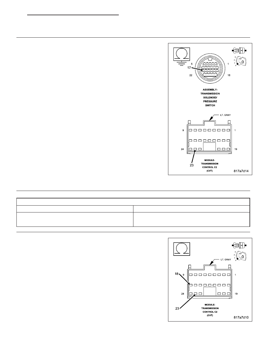
CHECK THE (T54) TRANSMISSION TEMPERATURE SENSOR SIGNAL CIRCUIT FOR A SHORT TO
GROUND

Turn the ignition off to the lock position.

Disconnect the TCM C2 harness connector.

Disconnect the Transmission Solenoid/Pressure Switch Assembly har-
ness connector.

Measure the resistance between ground and the (T54) Transmission
Temperature Sensor Signal circuit.

Is the resistance below 5.0 ohms?

Yes

>> Repair the (T54) Transmission Temperature Sensor Signal

circuit for a short to ground.

Perform CVT VERIFICATION TEST. (Refer to 21 - TRANS-
MISSION/TRANSAXLE/AUTOMATIC - CVT - STANDARD
PROCEDURE)

No

>> Go To 3

3.

CHECK THE (T54) TRANSMISSION TEMPERATURE SENSOR

Temperature Sensor Resistive Values Chart

Transmission Temperature

Resistive Value Compared to Temperature (± 10%)

20° C (68° F)

2.5k ohms to 6.5k ohms

80° C (176° F)

0.3k ohms to 0.9k ohms

Reconnect all previously disconnected connectors.

Start the engine and allow to obtain normal operating temperature
(approximately 10 min. of engine run time).

Turn the ignition off to the lock position.

Disconnect the TCM C2 harness connector.

Measure the resistance between the (T54) Transmission Temperature
Sensor Signal circuit and the (T13) Sensor Ground circuit in the TCM
C2 harness connector.

Is the resistance within the desired range listed on the above
chart?

Yes

>> Using the schematics as a guide, check the Transmission

Control Module (TCM) terminals for corrosion, damage, or
terminal push out. Pay particular attention to all power and
ground circuits. Check for any Service Bulletins for possible

PM

AUTOMATIC - CVT-ELECTRICAL DIAGNOSTICS

21 - 147

causes that may apply. If no problems are found, replace
the TCM per the Service Information.

Perform CVT VERIFICATION TEST. (Refer to 21 - TRANSMISSION/TRANSAXLE/AUTOMATIC - CVT -
STANDARD PROCEDURE)

No

>> Replace the Transmission Temperature Sensor (Valve Body) per the Service Information.

Perform CVT VERIFICATION TEST. (Refer to 21 - TRANSMISSION/TRANSAXLE/AUTOMATIC - CVT -
STANDARD PROCEDURE)

4.

INTERMITTENT WIRING AND CONNECTORS

The conditions necessary to set this DTC are not present at this time.

Using the schematics as a guide, inspect the wiring and connectors specific to this circuit.

Wiggle the wires while checking for shorted and open circuits.

Were there any problems found?

Yes

>> Repair as necessary.

Perform CVT VERIFICATION TEST. (Refer to 21 - TRANSMISSION/TRANSAXLE/AUTOMATIC - CVT -
STANDARD PROCEDURE)

No

>> Test Complete.

21 - 148

AUTOMATIC - CVT-ELECTRICAL DIAGNOSTICS

PM

P0713-TRANSMISSION TEMPERATURE SENSOR HIGH

For a complete wiring diagram Refer to Section 8W.

PM

AUTOMATIC - CVT-ELECTRICAL DIAGNOSTICS

21 - 149

Theory of Operation

The Transmission Control Module (TCM) monitors the Transmission Temperature Sensor Signal circuit for voltage
changes within desired limits. The TCM calculates the transmission fluid temperature from the temperature sensor
signal voltage. This value is used in conjunction with various other inputs to calibrate different operating modes such
as Torque Converter lock-up and Torque reduction.

The Transmission Temperature Sensor is a thermistor that changes resistive value when subject to different tem-
peratures. When the monitored voltage rises, the calculated temperature decreases.

When Monitored:
Ignition on engine running with battery voltage between 9.0 and 16.0 volts.
Vehicle speed greater than 10 Km/h (6 mph).
No secondary speed sensor or sensor ground DTCs present.

Set Condition:
Indicated temperature drops below -40° C (-40° F) for the continuous period of 5.0 seconds.

Possible Causes

(T54) TRANSMISSION TEMPERATURE SENSOR SIGNAL CIRCUIT SHORT TO VOLTAGE

(T54) TRANSMISSION TEMPERATURE SENSOR SIGNAL CIRCUIT OPEN

TRANSMISSION TEMPERATURE SENSOR

TRANSMISSION CONTROL MODULE

Always perform the CVT Pre-Diagnostic Troubleshooting procedure before proceeding. (Refer to 21 -
TRANSMISSION/TRANSAXLE/AUTOMATIC - CVT - STANDARD PROCEDURE)

Diagnostic Test

1.

CHECK TO SEE IF THE DTC IS ACTIVE

With the scan tool, read Transmission DTCs.

Is the status Active or is the STARTS SINCE SET counter 2 or less for this DTC?

Yes

>> Go To 2

No

>> Go To 6

2.

CHECK THE (T54) TRANSMISSION TEMPERATURE SENSOR

Turn the ignition off to the lock position.

Disconnect the Transmission Solenoid/Pressure Switch Assembly harness connector.

Ignition on, engine not running.

In the following step using the scan tool, monitor the Transmission Temperature voltage.

Jump the (T54) Transmission Temperature Sensor Signal circuit in the Transmission Solenoid/Pressure Switch
Assembly harness connector to ground.

Did the Transmission Temperature voltage drop from approximately 2.5 volts to 0.0 volts?

Yes

>> Replace the Transmission Temperature Sensor (Valve Body) per the Service Information.

Perform CVT VERIFICATION TEST. (Refer to 21 - TRANSMISSION/TRANSAXLE/AUTOMATIC - CVT -
STANDARD PROCEDURE)

No

>> Go To 3

21 - 150

AUTOMATIC - CVT-ELECTRICAL DIAGNOSTICS

PM


Content   ..  1210  1211  1212  1213   ..