Content .. 1212 1213 1214 1215 ..
Dodge Caliber. Manual - part 1214
2.
CHECK FOR ENGINE CAM OR CRANK SENSOR DTCS
With the scan tool, check engine DTCs.
Are there any Engine Cam or Crank sensor DTCs present?
Yes
>> Refer to the engine category and perform the appropriate symptom(s).
Perform CVT VERIFICATION TEST. (Refer to 21 - TRANSMISSION/TRANSAXLE/AUTOMATIC - CVT -
STANDARD PROCEDURE)
No
>> Go To 3
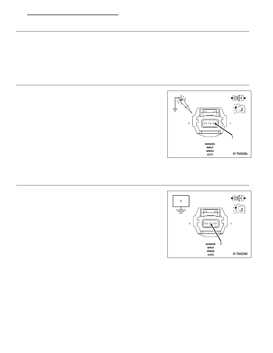
3.
CHECK THE (T16) TRANSMISSION CONTROL OUTPUT CIRCUIT FOR AN OPEN (HIGH RESISTANCE)
Disconnect the Input Speed Sensor harness connector.
Ignition on, engine not running
With the scan tool under TIPM, actuate the Transmission.
Using a 12-volt test light connected to ground, check the (T16) Trans-
mission Control Output circuit at the Input Speed Sensor harness con-
nector.
NOTE: The test light must illuminate brightly. Compare the bright-
ness to that of a direct connection to the battery.
Does the test light illuminate brightly?
Yes
>> Go To 4
No
>> Repair the (T16) Transmission Control Output circuit for an
open or high resistance.
Perform CVT VERIFICATION TEST. (Refer to 21 - TRANSMISSION/TRANSAXLE/AUTOMATIC - CVT -
STANDARD PROCEDURE)
4.
CHECK THE (T14) INPUT SPEED SENSOR SIGNAL CIRCUIT
With the scan tool under TIPM, stop the Transmission actuator.
Turn the ignition off, wait 5 seconds, then turn the ignition on.
Measure the voltage of the (T14) Input Speed Sensor Signal circuit.
Pick the answer that best matches your findings:
Voltage above 5.5 volts
Go To 6
Voltage below 4.5 volts
Go To 5
Voltage between 4.5 and 5.5 volts
Go To 7
PM
AUTOMATIC - CVT-ELECTRICAL DIAGNOSTICS
21 - 155